 |
|
| |
|
| VIP-Energy MANUAL VERSION 5 ENGLISH |
|
| |
|
 |
|
| |
|
|
|
TABLE OF CONTENTS
Introduction
Generic
Validation
Application manual
Data files in VIP-Energy
Calculation guide
Graphical interface design
Generic information
Main window
Input windows
Time schedules
Files
Catalog data
1-dimensional Building part
Windows, doors
Fresh air vents
2-dimensional building part
3-dimensional building part
Control of Solar protection, air permability, U-factor
Material catalog
Compound material
Form factors for wind pressure
Generic
Standard value
Calculation of wind pressure
Using catalog data
Operation cases
Energy price
Heat pumps
Type of heat sources
Refrigerant
Highest / Lowest temperature
Loss coefficient
Heat gas exchanger
Distribution
Test results and test standards
Solar collectors
Generic
Absorption coefficient
Loss coefficient 1
Loss coefficient 2
Accumulator volume
Temperatures
Circulation pump power
Accumulator simulation model
Solar cells
Generic
Efficiency
Temperature coefficient
Intensity coefficient
Highest and lowest cell temperature
Heat absorption coefficient
Heat capacity
Heat loss coefficient
Cooling machine DX-Cooling (Only available in validation mode)
Generic
Type of cooling system
Refrigerant / Compressor performance
Highest Lowest temperature
Temperature differences at condenser and evaporator
Test results
Cooling capacity
COP cooling / Supplied power
Temperatures
By-pass factor
Part load coefficient
Compressor efficiency
Air flow cooling fan
Power to condenser fan and pump
Upgrade catalog data
Import catalog data
Download Catalog data
Report Generator
Project data
Title
Climate information
City
Air pressure outside
Horizontal angle
Locked wind direction
Wind velocity % of climate file
Solar reflection from ground surface
Designing outdoor temperature
Load climate data
Building
Generic
Orientation
Rotation and tilting
Heat layers and share of heating demand
Ventilation volume
Floor area
Number of apartments
The angle towards south
Levels
Data import from VIP-Area
Time schedule for operation
Generic
Time schedules
Date function
Remaining time
Operation case
Operation hours
Operation year
Copy
Limitations
Time scheduled ventilation systems
Generic
Fan pressure
Fan efficiency
Operation hours
Operation year
Control case catalog
Generic
Lowest supply air temperature
Highest allowed supply air temperature
Energy efficiency exchanger
Efficiency recirculation
Regulation of flow from outdoor temperature
Cool recovery
Air supply from other zones
Connected to water heating system
Connected to DX-cooling machine (Only in validation function mode)
Connected to exhaust air heat pump
Fixed efficiency or heat exchange
Fixed efficiency for recirculation
Reduced recirculation at cooling demand(Only in validation function mode)
Highest temperature outdoor for reduced recirculation(Only in validation function mode)
Highest room temperature for reduced recirculation(Only in validation function mode)
Temperature controlled ventilation
Temperature controlled ventilation with passive forced flow
Forcing air flow over room temperature
Lowest difference temperature room-supply air
Total forcing flow supply air
Total forcing flow extract air
Fan pressure supply air
Efficiency supply air fan
Fan pressure extract air
Efficiency extract air fan
Temperature controlled ventilation with cooling (VAV system)
4.7.7.2.1. Lowest supply air temperature
4.7.7.2.2. Exchange efficiency
4.7.7.2.3. Controlling sequence
Heat supply
Generic
Solar Heating
Solar collector area
Angle to south
Inclination
Horizon angle
Heat supply
Restriction of heating capacity
Electric power circulation pumps
Water temperatures in heating system
Heat demand covered by water heating
Heat pump
Furnaces and boilers(Only validation mode)
Hot tap water
Consumption
Heat recovery
Temperatures
Energy efficiency
Cool supply
Generic
Passive cooling
Cooling machine water cooling system
COP cooling
Limit for free cooling
Cooling machine DX-cooling(Only validation mode)
District cooling
Power to circulation pumps
Maximum RH in room air
Cooling recovery for VAV forced exhaust air
Restriction of cooling capacity
Economy
Generic
Time schedules
Remaining time
Energy prices
Hours and weeks
Date function
Copy function
Restrictions:
Demands according to Ashrae 90.1 and LEED
Exposure an orientation of solar cells
Shading of solar cells
Calculate
Zone calculation
Generic
Initiation of supply centrals
Initiation of zones
Connecting supply centrals to zones
Connecting zones
Air temperature an moister transmission between zones
Common directory
Use catalog data from master file in all zones
Calculation
Results
Generic
Energy map
Result in time steps
Key Values and energy balance
Specification of energy flows
Economy
Report generator
Value export to text file
Graphical record
Pie chart supplied energy
Pie chart emitted energy
Bar chart energy balance
Bar chart duration diagram
Room temperatures
Multi zone calculation
Printing
Printing options
Calculation methods
Time division
Single zone model
Inherent heating systems
Solar heating systems
Heat pump
Default values
Compressor function
Heat exchangers
Testing standards
Heat gas exchanger
Energy sources
Geothermal (Rock)
Exhaust air
Ground source heat pump soil collector
Sea collector
Outdoor air coils
Heat distribution
Water heating system
Air heating
Accumulator tanks
Sequence control
Energy balance
Heating/cooling
Heating
Cooling
Air system
Air infiltration
Ventilation systems
Energy recovery
VAV-system Forced air flow at cooling demand
General
Priority of cooling
Priority of forced air flow
Condensation
Limit of available power.
Recovery
Heat capacity
Process energy
Transmission
Solar radiation
Ground models
2D- and 3D models
Orientation towards ground
Result presentation
Items of the energy balance
Presentation principals
Validation mode
References
Glossary
Appendixes
Appendix 1
Appendix 2
Appendix 3 Climate
Delivered climate files
File format:
|
|
| |
|
InfoCopyright: Strusoft 2020 Updated:2020-07-30 IntroductionGenericThe program calculates the energy consumption for buildings. All parts of the energy flow are calculated from known or measured facts. VIP-Energy is primarily intended for calculating the energy consumption of a building over a period of time usually covering one year but also shorter periods can be calculated. However, because the program is built around a dynamic calculation model with hourly calculation, instantaneous data for power, temperature and relative humidity are also available. 1.2 Validation The program as a whole is validated according to Ashrae 140-2007 and EN15265. Calculation functions for 2D and 3D models are validated according to ISO 10211:2007. Photovoltaic compute functions are controlled by comparison against the PV-SYST application. Examples and advice on applications This manual is limited to describing the contents of VIP-Energy. Input, result reporting, and a summary description of calculation functions. To this is a supplementary description how the program can be used in different situations. The PDF file with the description can be found under the menu "Applications" but can also be opened Here. |
|
| |
|
Data files in VIP-Energy Data for individual compute items is stored in project files with the ending .VIP. These project files contain project data such as catalog data and recent use of climate data for the individual compute object. When a user opens a project file, the application loads project data, catalog data, and climate data from that file. Therefore, there is no relationship between catalog data for different compute items. The catalog files in the catalog folder can be updated by the user choosing to export data from a project file. The catalog file update command is located under the Catalog Data menu. If catalog files contain data that is missing in a project file, that data can be imported. The "Import of Catalog Data" command is located under the Catalog Data menu. Imported data is added last to the compute object catalog. A set of latest catalog data is available on www.vipenergy.net and can be downloaded by selecting the download of catalog data under the Catalog Data menu. It works in the same way as importing catalog data. The program saves, at each calculation, temporary project files in the user's temporary files folder. Windows assigns each user a temporary files folder that is usually located under C:\Documents and settings\.......A link to that file can be found under the menu "Files". The temporary project file has the same name as the project file that the user saves but the ending. Tmp. It can be used directly if you change the "tmp" ending to "vip". Each time the user saves a project file over an existing file, the program saves the existing file with the VIPBU ending and that file is in the same folder as the project file. In cases where a project file cannot be loaded correctly, it cannot be saved or destroyed the current VIPBU file. The program contains a number of control stations at different levels for checking input. Dialog windows check the data that can be assessed for themselves. When calculating, it is verified that data from different dialogues are coordinated. |
|
|
|
Calculation guide Design building components that will be used in the project.Use VIP-Area to collect and organize amounts of building components like areas and lengths. Open Building data dialog under Project menu and import the data file saved in VIP-Area. Open Climate data dialog and choose climate file and feed micro climate data like wind protection and horizontal angle Open operation data and choose a appropriate time schedule or modify a new schedule. Eventually modify operation cases to fit the project. If there is a ventilation system open time controlled ventilation dialog and from that open ventilation control case catalog. Add a control case and set appropriate functions and values. For exhaust ventilation no functions has to be activated in normal case. Go back to ventilation window, add a ventilation unit with connected control case. Open time schedule dialog and hoose an existing time schedule for the ventilation unit or add a new one. Edit appropriate flow values. If there are some special equipment for heating or cooling those windows has to be edited otherwise they can be ignored. Calculate by opening the calculation dialog and if no error messages shows up click at calculation button. If he calculation is performed leave the dialog with OK and go to the dialogs under the result menu. |
|
| Top of page |
|
Graphical interface design |
|
Generic information |
|
By pressing the F5 key on the key board a calculation is submitted with current data wherever the user is positioned in the program. At the beginning of the calculation, data from different input windows are linked together. Names are used for identification. Only one input window can be open but all result windows can be open continuously. |
|
| |
|
Main window The main window opens when the program starts. It contains a number of menu choices in the upper part of the window.The name of the program (VIP-Energy), the project name (decided in Title), the current file, and the active window are shown on the title row. |
|
 |
|
| With the menu row, the user chooses a window by clicking on the adequate menu text. The corresponding window will open or a sub menu will be shown. Sub menus exist in several levels; the user opens the corresponding window by another click on a sub menu choice. Some menu choices can be marked in grey. This means that input data that has been indicated so far makes inadequate and the opening of the window has therefore been prevented. The tool bars in the left edge have links to input dialog windows. The tool bar in the right edge have links to result dialog windows. Files Functions for external communication with storage units, printers and some internet functions. View Settings for view of status-bar, tool-bar and program running mode. Catalog data Data that is common for different projects, like materials, building parts and technical equipments. Project data Data mostly specific for each project like size of building. Calculation sigle Calculation for a single zone like a family buiding. Calculation muliple zones Calculation for a larger building with zones with different climate properties. LEED calculation Calculation with caompaison to LEED reqirements. Results Shows the result of the calculation. Help Links to manual and license functions. Toolbars Tool bars in the main window offers direct access to the same function as menu choices. They are self instructing via the status bar in the bottom of the window and pop up tips. At program start the program version is checked and if there is a newer version an information is shown in the main window. The upper toolbar contain following buttons:  New project New project  Open existing project file Open existing project file  Save project file Save project file  Prewiev print layout Prewiev print layout
 Open manual Open manual  Wiev energy map Wiev energy map About VIP-Energy… About VIP-Energy…  Starta VIP-Area program Starta VIP-Area program
 Calculate directly Calculate directly  Print directly Print directly
The left toolbar contain buttons for input data dialogs: klimatdiagram  Outdoor temperature Outdoor temperature  Global horizontal radiation Global horizontal radiation  Wind sppeed Wind sppeed Relative humidity Relative humidity
Solar cells  Exposure and orientation Exposure and orientation  Catalog for solar cells Catalog for solar cells  Catalog for shading of solar cells Catalog for shading of solar cells
Building and its parts  Building Building
 1-dimensionell building parts 1-dimensionell building parts  2-dimensionell building parts 2-dimensionell building parts  3-dimensionell building parts 3-dimensionell building parts
 Material Material  Windows and doors Windows and doors  Control funkctions windows/doors, Solar shading, infiltration, U-vaule Control funkctions windows/doors, Solar shading, infiltration, U-vaule
Operating cases  Time schedule Time schedule  Catalog Catalog
Energy supply  Equipment for heat supply Equipment for heat supply Equipment för supply of comfort cooling Equipment för supply of comfort cooling
 Temperature controlled ventilation Temperature controlled ventilation  Time controlled ventilation Time controlled ventilation
 Energy prices Energy prices
 Demands connected to BBR Demands connected to BBR
Right toolbar contains buttons for resultat dialogs and diagrams.  Pie diagram supplied energy Pie diagram supplied energy  Emmitted energy Emmitted energy
 Chart diagram for energy balance Chart diagram for energy balance Duration diagram Total energy balance Duration diagram Total energy balance
 Room temperature Room temperature Operative temperature Operative temperature  Exhaust air temperature HP Exhaust air temperature HP
 PPD-Index summer climate PPD-Index summer climate
 Time devidesd energy balance Time devidesd energy balance  Total energibalance Total energibalance
 Key value Key value
 Energy supply Energy supply
 Solar power Solar power
 Comparison to demands Comparison to demands
 Costs Costs
 Custom report Custom report
 Export of data to text file Export of data to text file
|
|
|
|
Generic input window laout The user communicate with the program via input windows which can be reached via menu choice in the main window or icons in tool bars. With the  button the user can regret measures and with the button the user can regret measures and with the  button is it possible to go forward again. button is it possible to go forward again. Some input windows contains a list box (Red frame) and edit boxes(Blue frame). By clicking at a line in the list box data is copied up to corresponding edit boxes. By editing data the list box is simultaneous updated. By right mouse button click in the list box an context menu shows up (green frame). By clicking at add, delete or insert lines are controlled. Even the delete key at keyboard can be used to delete a marked line in the list box. A line can be moved by keeping left button down and drag the line to a new position. The Copy and Paste functions make it possible to copy data from one project to another. In several input windows there are buttons with links to other windows. In this example Compound material window can be reached from material window. |
 |
|
| |
|
Time schedules Time schedules for operation, ventilation and energy costs are saved in catalog data. The catalog can contain a number schedules for different type of activities. Each schedule can keep data for operation case, ventilation flows, and energy prices. It also possible to use separate schedule for operation, ventilation and prices. |
|
Files |
|
 |
|
New Project data will be erased and default catalog data will be loaded. Open Collect a previous stored project file. Save Save a project file with the current filename. The user must earlier have defined a file name under Save as. Save as Define a filename for a project file. Directory for catalog data A link to the directory where files whith catalog data, climate, and copy files are stored. Open Backup file Opens the directory where VIPBY files are located. Open last calculated single zone file Opens the temp directory that contains an extra backup file Start VIPArea Open the VIP-Area program. Start VIPclimate Starts an app that convert data til vipclimate format. Printing options Defines what is to be printed. Print Send to printer. Preview Preview printing before printing. Printer settings Choice of printer and settings of printer parameter; for example print-out quality. Exit Exit the program. |
|
View |
|

The option "Validating functions" open up input data windows that are used in the case |
|
Catalog data |
|
| 
When starting a new calculation, default catalog values from common catalog files will be fetched. After that every project gets individual catalog values. A change in catalog values in a project will therefore not influence other calculations. Unreasonable values will be checked automatically. |
|
1-dimensional Building component |
|
 |
|
| The menu item Building component catalog- 1-Dimensional building component are used to specify material composition, solar absorption, density and U-value. Walls, joists, roofs and floors of the building with one-dimensional heat flows are defined in this catalogue. The building components are in the order in which the user selects. It is not possible to define two building components with the same name, but you can have the same material name in a building component more than once. For building components with orientation INNER , Solar absorption, U-value (D-U value) and air permeability are not necessary for the calculation. The U-value does not include the D-U value Add new building components Right-click the list and choose Add or Insert. The program gives the new building component the same structure as the existing marked building component. Then you can revise the new building component. Copy/Paste With the right click on the top drop-down list, you will see a menu where you can choose to copy out a building component to a file "1DPart.vipcopy" that is placed in the folder for catalog files and climate files. The building part can then be pasted to other projects. Material layers building components with orientation "INNER1", energy flow to room air is calculated through the material surface of the last given material layer. For building components with orientation INNER2, energy flow is calculated through both material surfaces. The U-value in the building component list is updated for each material that is added. The materials in the building component must be defined in the material catalogue before calculation can be carried out. Material names can be entered by hand on the input line, but are advantageously retrieved by clicking on the Material Catalog command button, displaying a dialog box with a drop-down list containing all the materials defined in the material catalog. In the meaterial catalog list, you select which material you want to use, and press OK, and the selected material is copied into the input line in the correct place in the building component directory. The thickness is given manually. The user determines the order in which the building components are in the list. The program does not sort in alphabetical order. It is not possible to define two building components with the same name, but it is possible to have the same material name in a building component more than once. If a selected material does not exist in the material catalog, it is written in parentheses. In these cases, no U-value is written for the current building component. More information about the material dialogue can be found under the heading Material. Heat layers The program includes a function for simulation of built-in heating systems e.g. underfloor eating. In each building component you can insert a heat layer used for simulation heating pipes or electric-heating cables. The temperature in the heating layer can be regulated according to heating needs or with constant surface temperature. When regulating with regard to heating requirements, the "Building" dialogue indicates the proportion of each building component to provide of the total power requirement. This then provides the basis for calculating the required temperature in the heating layer. When regulating with regard to constant surface temperature, the "Building" dialogue indicates the surface temperature in the adjacent temperature column. To insert heat layers into a building component, press the Insert heat layer button. A heat layer is then inserted where the cursor is located. Use Remove heat layer to remove it. The check box for water-borne heat means that the building component is connected to the water heating system and can be fed from heat pumps connected to water-borne heat. U values Any changes made to the material list will cause an update to the U-value of the building component. There is an association between this catalog and the Input Building menu option, which means that any changes made to catalog data affect project data. For example, the U-value is also updated in the input dialog Building when changing e.g. thermal conductance. The program sets external and internal heat transfer resistance to 0.04 and 0.13 m²K/W respectively. D-U values Delta-U values can be used to adjust the U-value resulting from the thickness and thermal conduction ratio of the material layers. The program adjusts the heat conduction ratio of the materials taking into account the adjusted U-value. Material layer image The materials can be assigned to colors used in drawing the figure. Solar absorption Absorption coefficient of solar radiation to the outside of the building component. Total reflective white surface has value of 0 % Total absorbent matte black surface value 100 % Normal value for walls is 50-70 % Black roofing paper has about 90 % in absorption. Permeability factor q50 Air leakage of the building component in l/s, m2 at 50 Pa pressure difference. Normally the value is between 0.4-0.8. If extra measures are taken, it may be lower and if it is higher there will usually be comfort problems. Air gaps The program has no function to directly specify heat resistance for air gaps, but this may be converted into a thermal conduction number that becomes specific to each layer thickness. Air gaps are normally only inserted if they are not ventilated against outdoor air. In structures, air layers are normally ventilated against outdoor air. For non-ventilated layers, heat resistance and heat conduction ratios as shown in the table below can be used.
| Layer thickness [m] |
Thermal resistance [m²K/W] |
Thermal conductance [W/m] |
| 0,005 |
0,1 |
0,05 |
| 0,01 |
0,13 |
0,077 |
| 0,02 |
0,15 |
0,133 |
| 0,05 |
0,16 |
0,313 |
| 0,1 |
0,15 |
0,67 |
Limitations:
| Value: |
Min: |
Max: |
Unit |
| Absorb coeff: |
>=0 |
<=1 |
|
| D-U-value: |
>-U-value |
<=1 |
W/m2C |
| Infiltration: |
>=0 |
|
l/m2s |
| Thickness: |
>0 |
|
m |
|
|
Building component windows, doors |
|
 |
|
| General Parameters for windows, doors and parameters for Glass share, Transmittance, U-value, Air permeability and Shading. Information on solar transmittance is in the appendix or can be fetched from glass manufacturer. TST is the share of the external radiation that reaches the room. ST is the share of external radiation that reaches the room as radiation. The remaining quantity reaches the room as convective heat. Add new building component Right-click the list and choose Add or Insert. The program gives the new building component the same structure as the existing marked building component. Then you can revise the new building component. Copy/Paste With the right click on the top drop-down list, you will see a menu where you can choose to copy out a building component to a file "WDOPart.vipcopy" that is placed in the folder for catalog files and climate files. The building comonent can then be pasted to other projects Glass share The value indicates the proportion of the total space made up of glass. It affects the amount of solar energy through the window. Solar transmittance Information on solar transmittance can be found in Appendix 1 or can be obtained from glass manufacturers. Total transmittance indicates the percentage of heat that goes through the glass and is denoted in literature as usually g or TST. Direct transmittance indicates the proportion that reaches in the form of direct radiation to the interior surfaces of the room. The remaining amount reaches the room as convective heat to the room air. Normally, 70 % of the g-value specified by glass manufacturers is indicated to take account of normal sun protection measures such as blinds and curtains. Doors To define a door, set the values of solar transmittance to zero (0) Limitations:
| Value: |
Min: |
Max: |
Unit |
|
| Glass share |
>=0 |
<=100 |
% |
|
| Total transmittance |
>=0 |
|
% |
[Enclosure 2] |
| Direct transmittance |
>=0 |
|
% |
[Enclosure 2] |
| U-value: |
>=0 |
|
W/m2C |
|
| Infiltration: |
>=0 |
|
l/m2s |
|
|
|
Fresh air vents |
|
 |
|
General This dialog defines catalog data for outdoor air vents and other leaks that should not be assigned to an area. Outdoor air vents do not count towards the climate shell permeability when compared to requirements for leaks. Input is given for the airflow at 50 Pa pressure difference. Such large internal suppression is unusual and in the table the flow has been calculated at lower pressures. Normal internal suppression in exhaust air vented buildings is 10-20 Pa. |
|
2-dimensional building component |
|
 |
|
| VIP Energy contains a calculation function for 2-dimensional building components. The figure example shows a corner in a concrete sandwish wall. 2 dimensional building components are used and quantified the same way as the 1 dimensional ones except that quantity is in m instead of m2. The width is only used in combination with the length to calculate the envelope area for the building. Build the model by entering X- and Y- coordinates for each material in the construction. External and internal air is entered by reserved names OUTSIDE and INSIDE, marked as blue and red fields. The thickness of the 2D-model in z direction is always 1 m. For the U-factor calculation the program enters the inside and outside heat transfer resistance to 0, 13 and 0, 04 m²K/W. The model is drawn in a graphic window when the values are entered. Click on one point in the picture and the pictures coordinates are being transferred to an in data dialog. Snap interval can be set to minimum 0,001 m, which means that the coordinates is transferred in millimeter. A snap interval of 0, 01 means that coordinates are transferred in even centimeters. When clicking on Calculate the specific heat flow is calculated trough the model and is presented as a psi-value W/mK There are two alternatives for using 2-dimensional building parts in calculations. Alternative 1: The program creates an equivalent material and displays thermal conductivity, heat capacity and density that are used in energy calculations. The total energy flow is presented as a Psi-value. Alternative 2: If the user assigns a 1-dimensional building componnt as a reference then the program calculates the difference between the 1-dimensional component and the 2-dimensional component. The difference is presented as a Psi-value. If alternative 1 is used without a reference value then the 2-dimensional building part is handled like an ordinary wall with heat capacity. If alternative 2 is used then the program handles the building part in a simplified model just like doors without heat capacity. The program calculates an asymmetric index as a measurement of the model´s asymmetry towards the borders that are supposed to be symmetric lines. Symmetric lines are the borders where the model is not connected to inside or outside air. Energy flows are supposed to be natural parallel to the borders but if the model is too small the model forces flows to be parallel. An asymmetric index should be less than 5% for the model not to be affected by a narrow cut around the 2- dimensional areas. |
|
 |
|
| When Node lines with energy flows are checked the program shows calculated node lines with colors that represent energy flows quantities in W/m2. The scale is divided in ten colors. |
|
 |
|
| When Node with energy temperatures are checked the program shows calculated temperatures in a scale from from outside to inside temperatures which is specified by the user. |
|
| |
|
|
|
3-dimensional building components |
|
 |
|
| The figure shows a balcony connected to the slab with reinforced concrete partly broken by insulation. 3 dimensional components is used for specifying material and solar absorption; air permeability and U-value that sometimes known as thermal bridges. The area value is used for calculating the total envelope area. 3-dimensional components are used as a 1 dimensional components with the exception that it is the number of units that are calculated instead of m2 Material is retrieved from the material database. The model is built up by entering X, Y and Z coordinates for the material in the construction. Outside and inside air is entered by the reserved names OUTSIDE and INSIDE, marked as blue and red fields. For the U-factor calculation the program enters the inside and outside heat transfer resistance to 0, 13 and 0, 04 m²K/W. The graphical display is drawn when material is added to the construction. Click in the picture and the coordinates in that picture are transferred to an in data list and edit windows. A 3-dimensional picture is also drawn when material is edited. This upper left 3D picture is for information only and the content cannot be edited or selected in this picture. The calculation is done for the visible parts of the material. Material can be overlapped in each layer. The total energy flow through the model is presented as a Chi value W/K. |
|
 |
|
| When Temperature is checked, the program shows calculated temperatures with colours that show the temperature in each section. When clicking on Calculate the specific heat flow is calculated trough the model and introduced as W/K. |
|
4.6.6. Control functions for solar protection, air permeability, U value |
|
 |
|
| General The control functions are used for the building components in the Window/Doors catalogue. It is a catalogue of control functions for sun protection U values and permeability factor, as well as associated control parameters. At least one of the conditions for room temperature, outdoor temperature or solar power against façade shall be met to activate the control functions. It is solar power perpendicular to the window referred to. If the wind speed exceeds the set value, the control function is disabled. If this feature is enabled, values in the control catalog apply. Otherwise, values in the window/door catalog will apply. Add new control function Right-click the list and choose Add or Insert. The program gives the new record the same build up as the existing selected record. The new directory entry can then be revised. Copy/Paste With the right click on the top list, you will see a menu where you can choose to copy out a control function to a file "WDOControl.vipcopy" that is placed in the folder for catalog files and climate files. The control function can then be pasted to other projects. Screens Screens are used to simulate moving sunshades such as awnings and fixed as balcony plates. To simulate fixed screen, it is easiest to activate it with solar power and the value is set to 0 W/m². Solar transmittance Used for sunscreen simulation that covers the entire window and is independent of angles. The value refers to total transmittance for sunscreen and windows. It is independent of the transmittance of the window without sunscreen. Permeability factor The most nearby application is simulation of airing. U value In some cases, the choice of sunscreen also affects u-value. For example, blinds between windows usually contribute to reducing the U-value |
|
| Limitations:
| Value: |
Min: |
Max: |
Unit |
|
| Shield angle: |
>0 |
<180 |
degr |
|
| Wind speed: |
>=0 |
|
m/s |
|
| Transmittance |
>=0 |
|
|
|
| Air permeability |
>=0 |
|
|
|
| U-factor |
>=0 |
|
|
|
| Solar power |
>=0 |
|
|
|
|
|
Material catalog |
|
 |
|
| General The Material Catalogue specifies materials of which the building components in catalogue 1-, 2- and 3-dimensional componenst are constructed. Add new material Right-click the list and choose Add or Insert. The program gives the new material the same structure as the existing marked material. you can revise the new material. Copy/Paste With the right click on the list, you will see a menu where you can choose to copy out a material to a file "material.vipcopy" that is placed in the folder for catalog files and climate files. The material can then be pasted into other projects. Thermal conduction ratio Thermal conduction ratios are sometimes also called lambda value and indicate the thermal conductivity of the material. Density and heat capacity The calculation uses density and heat capacity to calculate the building's heat storage capacity. Density can usually be retrieved from data sheets for materials. Data on heat capacity that is more dependent on the base material can be obtained from building manuals. Material cost The material cost can be given any unit but is always linked in the calculation to the material weight. This function can be used to calculate economy, environmental impact such as the amount of CO2. Material colour Material colour is used to define colors that are used when drawing shapes in building part catalogs or in result printouts. The color dialog contains a number of standard colors and with the narrow button at the bottom of the dialog, a dialog window is reached where any color can be selected. Limits:
| Value: |
Min: |
Max: |
Unit |
| Thermal conductivity |
>0 |
|
W/mC |
| Density: |
>0 |
|
kg/m3 |
| Heat capacity: |
>0 |
|
Ws/kg |
|
|
Compound material |
|
 |
|
| General The function is used for 3 dimensional calculations of resulting composed material properties in building componens with two material layers in two directions. A description is made for a composition that consists of one or two layers. Each layer contains two materials where the user chooses type, width and height of a material. Calculation Pressing the” Calculate” button the thermal-conduction, heat-capacity and density will be calculated. The OK-button is activated when the calculation is finished. If ending the dialog with OK, the calculated values and inputs will be stored in the material that was marked in the material list when the dialog was opened. Current composed material is to the top the dialog window. Width and height must always be larger than zero though a thickness of a layer can be zero. Example The figure below shows a stud wall with standing and lying studs. The calculation is performed on a representative part. The boundaries are drawn in symmetry lines where the heat flow runs parallel through the wall. The example shows the smallest slicer needed for a calculation. A half compartment of the width and height has been included. It will be the same result as bringing a whole wall.  If the wall has only standing studs, you take with an arbitrary height and select the thickness of layers two to 0 mm. Sheet metal profiles The figure shows a sheet metal profile, stud or runner. It can be replaced with a solid profile with the same dimensions and with material data that gives the same thermal conductivity as the sheet metal profile. For slotted steel profiles, the thermal conductivity is dependent on the design of the slots and the manufacturers' accounting of characteristics is referred to. There is rarely data for individual profiles that can be directly used in calculations, but for some brands there is data on U-values for individual design types. From this, thermal conduction rates for individual profiles can be derived. The table below shows the thermal conductivity W/m K for profiles with profile width 145-250 mm and plate thickness 0.7-1.5 mm. Data applies to normal studs and runners. Profile width is the same measure as layer thickness in input. For special profiles, such as reinforced studs, the value may be higher as these may be less slotted. There is generally a lack of data, but one estimate is that thermal conduction rates should be doubled for those types of profiles.
|
Plate thickness mm |
Profilw width mm |
0,7 |
1,0 |
1,2 |
1,5 |
145 |
0,11 |
0,13 |
0,16 |
0,18 |
170 |
0,12 |
0,15 |
0,17 |
0,19 |
195 |
0,14 |
0,17 |
0,2 |
0,23 |
250 |
0,16 |
0,19 |
0,24 |
0,3 |
The fact that the thermal conductivity increases for increased plate thickness feels natural, but it also increases for increased profile width and insulation thickness. It is likely to depend on the design and amounts of the slots. The density of the material is set at 7800 [kg/m³]*sheet thickness [mm]/50. The heat capacity is not affected but is the same as for solid material. If the design of the slots is known, it is possible to use the 3D function of the program to calculate the thermal conductivity for specific products. Sheet metal studs without slots are less complicated and can be calculated based on sheet metal thickness. For steel studs, the thermal conduction ratio is set to 60 [W/mK]*sheet thickness[mm]/50. The material is then used in for the calculation of composite materials. Limitations
| Width |
<100 |
| Height |
<100 |
| Layer thikness |
>0 |
|
|
|
|
Form factors for wind pressure |
|
 |
|
| |
|
Generic |
|
| This dialog is used for editing wind pressure form factors. Form factors affect facade wind pressure which is one of the parameters when calculating air leakage. The angle of incidence is the angle between the wind direction and the orientation of the surface. It is not possible to delete or add an angle of incidence. A 0° angle of incidence refers to wind on the surface. A wind direction of 180° means that the surface is completely sheltered from wind. Roofs have a form factor of their own. |
|
|
|
Standard value
| Orientation |
Form Factor |
| To windward |
0,7 |
| Leeward |
-0,5 |
| Sides parallel to the wind direction |
-0,6 |
| Roof |
0 till -0,2 |
|
|
Calculation of wind pressure |
|
| Pv=FF*Pd Pd=*v2/2 Pv Wind pressure [Pa] Pd Dynamic pressure [Pa] FF Form Factor Air density [kg/m3] |
|
| |
|
Using catalog dataThe orientation of the building parts are set in In data>Building and that in combination with climate data determines the wind pressure for the building component. |
|
| |
|
Operation cases |
|
 |
|
| |
|
| General Operating cases are used to specify process energy, person energy, moisture supplements, thermostat settings for the maximum and minimum values of the room temperature, thermostat setting for passive force of ventilation and energy for hot tap water. Add new operating case Right-click the list and choose Add or Insert. The program gives the new operational case the same structure as the existing marked operating case. Then you can revise the new material. Copy/Paste With the right click on the top drop-down list, you will see a menu where you can choose to copy out a building part to a file "Operationcase.vipcopy" that is placed in the folder for directory files and climate files. The building part can then be pasted to other projects. Process energy Process energy is energy use that is controlled by the activity regardless of climate requirements. Activity energy to room air and operation energy, is treated in the same way in the calculation, but the breakdown is conditioned by how the amounts of energy are to be valued when calculating specific energy use according to BBR. Operation energy is included in specific energy use to be compared with requirements. However, activity energy does not. Of the activity energy, and operation energy, some can be specified to go to room air and some to be emitted externally without the influence of the construction energy balance. The user can control whether process energy should be supplied as radiation to building parts or convectively to the room air. Normally, all energy is added convectively to the room air and the proportion of heat radiation is set at 0%. Person energy Person energy is supplied to the room air in parallel with activity energy and operation energy. The difference is that person energy is not included in the calculation of energy costs. Moisture supplements The value indicates moisture supplements to the room air. The moisture content affects the recovery of heat from exhaust air with exhaust air heat pump and cooling functions associated with return air. Moisture supplements can condense and freeze to ice in plate heat exchangers if calculation is carried out according to EN308. Evaporation and condensation of moisture are presented in results as latent energy. Evaporation heat for moisture at room temperature is 2500 kWs/kg. Example: Normally, 2 g/kg of moisture is added to the room air in homes. This applies to standard ventilation 0.35 l/sm² and normal person density. The volume flow of 0.35 l/s,m² corresponds to the mass flow 0.42 g/s,m². To reach 2 g/kg, the moisture input is set to 0.84 mg/s,m². Hot tap water The program sums up the amount of energy for hot tap water that is part of the energy demand. Energy for hot tap water is not supplied to the room air, but is released entirely as waste water. Room temperatures The hours room temperature tend to go below the minimum temperature heat is added. The hours of room temperature tend to go above the maximum allowable temperature cold is added. Minimum temperature can be adjusted to take account of regulation losses in the dialogue Heat supply. The lowest and maximum temperature values are the temperatures that will occur in the building. As a rule, the minimum temperature is slightly higher than the minimum permissible temperature due to incompleteness in control functions. This applies specifically to regulation with self-acting thermostatic valves on radiators that need some degrees temperature rise to close completely. Normally, an increase of the minimum room temperature of 2 °C should be sufficient to cover incompleteness in thermostatic valves. Electronic regulation can be made more precise. When calculating underfloor heating, the program simulates the control inertia of floor heating and the user only needs to take into account the incompleteness of the regulated area. Minimum temperature passive force The value indicates at what room temperature passive force can be activated. In order for activation to take place, the other conditions specified in the dialogue for temperature-controlled ventilation must also be met. Use of catalog data Under Project data>Operation Temp/process energy, operational cases are put into a time schedule. Limitations |
|
| Value: |
Min: |
Max: |
Unit |
| Max temp: |
>=Min temp |
|
C |
|
|
|
|
Energy price |
|
 |
|
| Various energy rates can be told for: Heating of room, inlet air and hot water. Process energy Electric energy for heat pumps and fans. District cooling In order to specify combinations of rates for different energy types. The user chooses the type which for example can be kgCO2/kWh.
If /kWh exists in the unit, it will be taken away when the cost is presented. Then there will be a presentation in dollar or kg CO2 only. |
|
|
|
Heat pumps |
|
 |
|
| The dialog is used for creating a catalog for heat pumps that can be used under In data>Heating & Cooling. |
|
Type of heat sources |
|
| VIP-Energy consider 8 types of heat sources: Exhaust air Gets heat from exhaust ventilation flows. Gives heat to water heating system. Geothermal, Rock Gets heat from rock holes. Gives heat to water heating system. Ground source Soil Gets heat from collector pipes in soil. Gives heat to water heating system. Sea heat Gets heat from collector pipes in sea water. Gives heat to water heating system. Air/Water DX Gets heat from fan coil out door. Gives heat to water heating system. Air/Air Gets heat from fan coil out door. Gives heat to fan coil in room air. Air/Water Brine linked Gets heat from fan coil out door. Gives heat to water heating system. Exhaust air/Supply air Gets heat from exhaust ventilation flows in the ventilation unit it is linked to. Gives heat to supply air in the same unit. |
|
RefrigerantData sheets contain what type of refrigerant they use. |
|
| |
|
Highest / Lowest temperature The heat pump works within those limits. Otherwise it will shut off. |
|
| |
|
Loss coefficientFor some of the outdoor heat pumps water heating system is connected to the outdoor unit. That results in some extra losses from the water heating system. |
|
| |
|
Hot gas exchangerSome heat pumps has an hot gas exchanger that recover the hot gas from the compressor to hot tap water even during the time when the compressor deliver condenser heat to the water heating system at a lower temperature. |
|
Control of speed and power
For some heatpumps it is possible to vontrol compressor speed an power whithin sertain limits.
For some exhaust air heat pumps it can even be possible to control speed depending on exhaust air temperature in purpose to avoid frost generation in the evaporator. |
|
DistributionThe heat pump can be connected to the water heating system and the hot water system. The connection between the water heating system and ventilation units, radiators and underfloor heating system is specified in catalogs for each unit. |
|
| Share of space heaters linked to water heating system A portion of the power demand for space heating can be supplied from underfloor heating systems. Depending on the selected minimum supply air temperature, part of the power demand can be taken care of by the supply air. Remaining power demand for space heating is taken care of by space heaters or Air/Air heat pumps. Space heaters can be radiators, convectors, fan convectors, air heating systems etc. Some of these space heaters can be connected to the water heat heating system, others may be electric heating, stoves etc. Input for "Share of room heaters linked to water heating system" specifies how much of this remaining power needs to be taken care of by space heaters that are connected to the water heating system and thus can be reached by heat from the solar collectors and heat pumps and associated with water heating systems. If the share connected to water heating system is less than 100%, there is a space for air/air heat pumps. The share of power demand that are not covered by water heating system or Air/Air heat pumps are not defined and can be electric heating-heaters, fireplaces, etc. See more about heat pumps under Chapter 6.5 |
|
Test results and test standardsHeat pumps is usually tested according to at least one of the standards EN 14511. Test results is used for input to VIP-Energy. Power to pumps and fans can be included or excluded in test results. |
|
|
|
Solar collectors |
|
 |
 |
|
| |
|
GenericSolar heating is calculated considering input data in the form of solar radiation from climate file, horizontal angle, the orientation and inclination of the solar collector. |
|
Absorption coefficientThe value states how big share of the radiated solar energy that will be absorbed. The program calculates how big share that will be prevented and reflected by the glass surface. |
|
Loss coefficient 1The value states, together with loss coefficient 2, the heat emission from the solar collector to the surrounding air due to the temperature difference. Unit: W/m2K |
|
Loss coefficient 2The value states, together with loss coefficient 1, the heat emission from the solar collector to the surrounding air due to the temperature difference. Unit: W/m2,K2. |
|
4.6.11.1.4. Accumulator volumeThe solar heating system has a separate accumulator tank to store heat. Input for volume is m3 per m2 collector area. |
|
TemperaturesInput for temperature limits within the system can work. At tank temperature under the span no energy is delivered to the system. Heat is stored up to the upper limit. |
|
Circulation pump powerThe circulation pump is working when the accumulator tank is loaded from the collector. The pump energy is calculated on loaded energy not delivered from the tank to the building. |
|
Accumulator simulation model (Only available in validation mode)In normal case the detailed simulation model is used. The model optimize the recover regarding temperatures in heating system and cold and hot water temperatures. The simple model is used for validation of calculation at certain temperatures. |
|
Solar cells |
|
 |
|
GenericThe dialog is used to specify the properties of solar cells that are used in Project data Solar cells-> Exposure EfficiencyThe efficiency indicates the proportion of incoming solar power which is converted into electricity in solar cells. The value applies to cell temperature 25 ° C and solar power 1000 W perpendicularly towards the solar cell. Temperature coefficientsThese coefficients indicates how the efficiency changes with the cell temperature. Coefficient 1 is working directly proportional to temperature change and Coefficient 2 to the square of the change. Intensity coefficient The coefficient indicates how the efficiency is affected by solar radiation intensity. Highest and lowest cell temperature The values specify the maximum and minimum temperature the solar cell to function. Outside this temperature range no electricity is produced Heat absorption coefficient The value indicates the percentage of incoming solar energy absorbed and converted to heat at the cell surface. Heat capacity Solar cells can be given a heat capacity that slows the temperature change by the change in impact. Heat loss coefficient The value specifies emitted heat in relation to normal heat emission from one side. |
|
| |
|
Upgrade catalog data |
|
|  The dialog can be used for upgrading the catalogs that are used for starting new calculations. The catalog (or catalogs) that is going to have the same values as the current calculation is marked in a check box. The dialog can be used for upgrading the catalogs that are used for starting new calculations. The catalog (or catalogs) that is going to have the same values as the current calculation is marked in a check box.
|
|
| |
|
Import catalog data |
|
| 
The dialog can be used for importing data from catalogues. Data that does not exist in “current data” is imported to the end of the list. |
|
Downloading directory data from vpd files on www.vipenergy.net  This feature is similar to Directory Data Import, but in this case, data is retrieved from files located on the www.vipenergy.net. In this feature, data types that are normally created by users have not been included. |
|
|
|
Report Generator |
|

The user can use the dialogue to customize reports based on all data in the energy calculation. Every report or summary is named and under that name all fields (or energy flows in the model) can be added or subtracted. In each report, a field can only appear once. In the result menu the user can select to show the appropriate reports. |
|
| |
|
| Top of page |
|
| |
|
Project data |
|
All data except title must be accepted before the calculation can start. The result is lost if the user changes the input data. |
|
| |
|
Title |
|
 |
|
| This dialog window contains description and comments about the project. Data has no impact on the calculation. Project name will be the title of the result print. Description is used for a shorter description of the current calculation. Comment is a text area for elective information for the user about current project. Date is filled in from the computer’s internal watch at a new calculation. Date, sign, project name, description an comment is stored in the project. User, User company and Sign is filled in by the user and stored in catalog file. The information is stored under “Update catalog data” and a check for User Data |
|
| |
|
|
|
Climate information |
|
 |
|
| Restrictions:
| Value: |
Value: |
Max: |
Unit |
| Horizon angle |
<0 |
<=90 |
degrees |
| Air pressure |
>0 |
|
hPa |
| Wind speed |
>0 |
|
% |
|
|
City |
|
The user chooses City by election from a combined text and list box with cities where climate data is available. The program can be completed with further climate data which will be delivered by SMHI or Meteonorm. When the city has been chosen climate data will be shown in a graphic picture which can show either outside temperature, solar radiation, wind velocity or relative humidity. |
|
| |
|
Air pressure outside |
|
The user can adjust for level over sea with air pressure. Air pressure has an impact on air density as well as on heat transport. The pressure is sinking with 1 hPa for every 8 meter up to 500 meter over sea level. Normal air pressure at see level is 1013,21 hPa. |
|
| |
|
Horizontal angle |
|
Shading is given by feeding the horizontal angle for eight sectors. Shading is used for calculation solar radiation.  |
|
| |
|
Locked wind direction |
|
The software can get the wind direction from a climate file if that contains necessary data. The locked direction will be used when using an older climate file that does not contain wind direction or when the local main wind direction is different than at climate station. The user can always lock the wind direction by using the check box. |
|
| |
|
Wind velocity % of climate file |
|
The value tells how big share of the wind load of the climate file that hits the building. |
|
| |
|
Solar reflection from ground surface |
|
The value represents the share of solar radiation reflected from the ground towards the building. A dark surface has a low value and a water surface has a high value. Normal values are 20-50 %. |
|
| |
|
Designing outdoor temperature |
|
Input for designing outdoor temperatures for heating and cooling. If the outdoor temperature exceeds the maximum temperature for cooling the room temperature limit is following up. The same happens for low temperatures and heating. |
|
| |
|
|
|
Building |
|
 |
|
| |
|
Generic |
|
The building dialog window is used to combine building parts to a building. Amount of building parts an there orientation is needed. If the building part contains a heat layer the heat layer load is defined as a share of total heat demand to room air. The input of building parts can be written directly in the edit box or copied from one of the catalog windows with the commanding buttons under the list box. By clicking one of these button a dialog box will show up with the content of the catalog. With a click on one of the rows and then one click on OK, the building part will be copied in the right box in the input row. The framed input windows for heat transfer are only available on validation mode. |
|
 |
|
Orientation |
|
The orientation INNER1 and INNER2 is used to describe the interior building parts where both sides have contact with indoor temperature. Construction parts has an inner and outer side. It's the last specified material layer, which is defined as the Interior. If INNER1 is selected heat exchange is calculated only between current zone and the inner surface. The outer surface is in this case assumed as border towards another zone with the same temperature as current. If INNER2 is selected heat exchange is calculated between current zone and both surfaces. The orientation is chosen for the interior walls and intermediate floor within current zone. For INNER1 and INNER2 orientation the Lowest level and Highest level will be inactive and the values will not be used in the calculation. Inner walls can be used as separating walls between the rooms that are included in the calculation and towards adjacent rooms with same temperatures. All building parts, inner and envelope, are interacting by heat radiation. So inner parts are important both as heat capacity and heat exchange between room air and envelope via radiation from inner to envelope surfaces. If TEMP is used as orientation, the building part will be calculated as a border to another room with a constant temperature like cooling room. In building code contexts TEMP building parts is sorted as envelope. The orientation TEMP-I has the same function as TEMP with the exception that TEMP-I is not involved in the envelope area. When using TEMP_O stand for outdoor temperature independent of solar radiation and the area of the building part is excluded from the envelope area in building code context. Compass point orientation are facing outside surface temperature which are depending on solar radiation and outdoor temperature. Orientation contains a number of alternatives of calculation of building parts towards ground. The choice of underground properties influences the calculation of transmission through ground. |
|
 |
|
SOG: Slab on grade BW: Basement wall BF: Basement floor ROOf is treated as horizontal surface facing upward. For tilted roof use compass point and tilting function. |
|
| |
|
Rotation and tilting |
|
Each building part can be rotated and tilted separately. Zero value for tilting means that surface is vertical. Tilting value is only valid for compass point orientations. |
|
| |
|
Heat layers and share of heating demand |
|
For using a heat layer in the building construction the percentage part of the needed power that the heat layer should cover must be stated. The design of the building part is directly reflected in the energy consumption. If the heat layer is close to heat accumulating material the user will get a control inertia that can counteract energy savings. On the other hand, less insulation outside the heat layer can increase the need of heat transmission of the building. In this dialog the U-factor including delta U is shown. |
|
| |
|
| Ventilation volume |
|
Used for calculations of airflows in ventilation systems. The ventilation volume is multiplied with the number of changes per hour that will be fetched from Time controlled ventilation and Temperature controlled ventilation. The volume i even used for calculation of relative humidity that has an effekt on exhaust air heat pumps and latent part och energy for comfort cooling. |
|
| |
|
Floor area |
|
The area is multiplied with the quantity of energy per square meter that will be fetched from Catalog data- Operation cases and ventilation given as l/s, m² or m³/ h,m². |
|
| |
|
Number of apartments |
|
The number of apartments can be used in operation case catalogue to describe process energy and hot tap water. |
|
| |
|
The angle towards south |
|
The angle towards south is the angle between the surfaces having been given the direction SOUTH and the real angle towards south. If the building is turned clockwise the angle will be positive. |
|
| |
|
Levels |
|
The levels are the altitude localization of building parts and is needed for simulation of infiltration depending on stack effect. It is the height of cohesive air volumes that decides how levels are chosen. Normal values for 1 story apartments are 0-2,4 m. For an internal open office building the values can cover the whole building height. |
|
| |
|
Data import from VIP-Area |
|
The VIP-Area software is installed along with VIP-Energy. VIP-Area is used to organize measuring and calculation of amounts like areas and lengths. Data is stored in mngd-files that can be imported to VIP-Energy. Information about VIP-Area is in a separate manual. |
|
| |
|
|
|
Time schedule for operation |
|
 |
|
| |
|
Generic |
|
The dialog is used for organizing hours for predefined operation cases. All hours of the year must be covered and they cannot overlap. The colored fields is a help function to find out how much time is missing or overlapping. The bottom left field of the dialog has 53x24 squares and is valid for the with the tabs chosen day of the week. Each square represents one hour of the chosen day. Light or dark green squares indicate that the input is OK, yellow squares indicate hours that have no input, and red squares indicate double input. The field for each day of the week gives an overview of the input. |
|
| |
|
Time schedules |
|
Operation hours are stored in time schedules that can be stored as catalog data. A time schedule which is created for operation cases is even available under Economy and Time controlled ventilation. |
|
| |
|
Date function |
|
The function is used to translate date to week number. Operation times and operation cases are stated in seven dialog tabs, one for each day of the week. |
|
| |
|
Remaining time |
|
It is also possible to state an operation case for remaining time, i.e. hours that is not stated in the table. The function reduces the amount of work for schedules with a base operation case which is completed by different other cases. |
|
| |
|
Operation case |
|
Names for predefined operation cases can be retrieved from the Operation Case Catalog by pressing “Control Case Catalog”. The name will be copied into the right input box with a click on a row in the catalog list and then press OK |
|
| |
|
Operation hours |
|
Start time and end time must be within the same day and is valid from start week to end week. The start time is therefore always to be less than the end time. All 53 weeks has to be covered. |
|
| |
|
Operation year |
|
The software retrieves information on the connection between weekday and date for chosen operation year from the calendar function. If January 1st happens to be e.g. a Wednesday then the calculation will start with Wednesday. |
|
| |
|
Copy |
|
It is possible to copy data between the days of the week. If the user has chosen to e.g. copy Tuesdays from Mondays then even Tuesdays will be updated when Mondays are edited. |
|
| |
|
4.7.4.9. Limitations
| Value |
Min |
Max |
| Start week |
>=1 |
<End week |
| End week |
>Start week |
<=53 |
| Start time |
>=0 |
<=End time |
| End time |
>Start time |
<=24 |
|
|
|
|
Time scheduled ventilation systems |
|
 |
|
| |
|
Generic |
|
In the ventilation system dialog possible an arbitrary number of ventilation units can be added. Each unit can hold a ventilation flow schedule. Each day of the week can have a schedule of its own. Data is can be copied among the days of the week. Each unit has its own set of properties which are stated on the same line as the unit name. A unit that in real life is run with various properties during the day is stated as several units, one for each operation case. Control functions are being specified as separate control cases that are stored in a control case catalog. |
|
| |
|
Fan pressure |
|
Fan pressure is used in combination with efficiency for calculating consumed electric energy for the fan. Normal values for fan pressure extract air No heat recovery: 200 Pa Heat recovery: 500 Pa Normal values for fan pressure supply air: No heat recovery: 300 Pa Heat recovery: 600 Pa |
|
| |
|
Fan efficiency |
|
The efficiency states what work the fan has performed in relation to consumed electric energy. Normal value: 50-60% Fan efficiency is not to be mistaken for the efficiency for the heat recovery system. Electric power = fan pressure * flow / efficiency |
|
| |
|
Operating hours |
|
 |
|
For each ventilation unit, operating hours and flow are entered. Each unit has its own set of operating hours. Operating hours is stored in schedules that can be saved as catalog data. Schedules created for ventilation hours are also available for operating and energy tariffs. |
|
Operation year |
|
The software considers relations between weekday and date for chosen operation year. |
|
Time schedule ventilation General The input window is used to time control fan flows. Only hours with flows need to be specified. Remaining time In addition to specific weeks and hours, there is also the option to provide flows for remaining time, and this applies to weeks and hours that are not specified in the table. If a ventilation flow is used continuously, you can set it as remaining time. |
|
|
|
Control case catalog |
|
|
|
 |
|
| |
|
Generic |
|
Under the Time controlled ventilation dialog there is a dialog with control cases. Maximum and minimum for supply air temperature, heat recovery, air recirculation and flow regulation are controlled with consideration to two various outdoors temperatures. In the validation function mode there are some extra function that is not used in normal projects. The validation function mode can be activated under the View menu. |
|
| |
|
Lowest supply air temperature |
|
Lowest allowed temperature for supply air with consideration taken to condensation, comfort etc. The supply air temperature is raised to the stated value irrespective of room temperature. |
|
| |
|
Highest allowed supply air temperature |
|
Highest allowed temperature for supply air. Supply air temperature is lowered to the stated value. |
|
| |
|
Energy efficiency for exchanger |
|
The energy efficiency of the heat exchanger states the extent of the recovered amount of energy from the exhaust air. This is normally slightly less than the temperature efficiency when it comes to a raise of the supply air temperature in relation to the indoor-outdoor temperature difference. Standard values:
Rotating exchanger: 70-90%
Cross current plate exchanger: 50-60%
Counter current plate exchanger 70-90 %
Run-around Coil Heat Exchanger 50% |
|
Efficiency according to EN308 Normally you should use values measured according to standard EN 308. Indication of the efficiency at which flow the measured defines the exchanger properties. Efficiency is flow dependent and a recount is done internally by the program. Type of heat exchanger The program includes simulation models for the most common types of heat exchangers. Initially, the program creates a computational model of the exchanger with the test data according to a 308. Test data must contain efficiency and associated test flow that should be equal for supply air and exhaust air. Testing according to a 308 takes place without condensation or icing. The program calculates the hourly heat, condensation, icing and defrosting and moisture recycling in the light of current conditions. Defrosting method In the plate heat exchangers and Run-around coil changer frost is formed of the moisture which is added into the room air, if the outdoor temperature is a few degrees below zero. The program includes computational models of the most common methods to defrost the exchanger. Demand-controlled defrosting means that there is a function that records if it formed the frost and that reduces recovery by bypassing the cold outdoor air in plate exchangers or close the liquid flow in the Run-around coil exchanger as long as is necessary to melt the ice. The calculation simulates the optimal conditions. Therefore, there is the option to add a time margin. If nothing else is known the margin is set to 50%. Number of sections If the exchanger is defrosted through by-pass of the whole cold air flow the whole power of heating of outdoor air is transfered to heat coil. If the heat exchanger is divided in two halves power requirements for heating coil. Theoretically number of sections is limited depending on the time necessary for defrosting. If 6 min defrost requires per hour, it is not possible to use more than 10 sections. The program maximizes automatically number used sections, taking into account the estimated defrosting time. Information about defrosting method obtained from ventilation unit provider. More detailed information on heat exchangers are provided in section 6. |
|
Efficiency for recirculation |
|
The efficiency intends recirculation flow compared to extract air flow. Recirculation flow is maximized to supply air flow independent of efficiency input. |
|
| |
|
Regulation of airflow according to outdoor temperature |
|
The airflow can be regulated according to outdoor temperature. The flow is stated in % of the in the time schedule stated flow at two different outdoor temperatures. If the outdoor temperature is below or above the two given outdoor temperatures then value of the nearest outdoor temperature will be valid |
|
The regulation of air flow can be achieved by the fan speed changes with or without the restriction of air flow with a damper in the duct system. If the raegulation takes place without damper is the flow resistance is constant. Fan pressure changes proportionally to the square of the flow. Alternatively fans are controlled to constant fan pressure and flow by throttling the flow in the duct system. |
|
Cool recovery |
|
The heat exchanger will be used for cooling supply air when there is a need for cooling and when the extract air temperature is below the outdoor temperature if the box is checked. |
|
| |
|
Fresh air supply from other zones |
|
This option is for multi zone calculations. Fresh air temperature and humidity will be taken to the ventilation unit from a mixture of air from different zones and outdoor air. The mixture is specified in the in data dialog for zone calculations. If no share from other zones is stated outdoor air temperature will be used. |
|
Exhaust air supply from other zonesThis option is for multi zone calculations. Exhaust air temperature and humidity will be taken to the ventilation unit from a mixture of air from different zones. The mixture is specified in the in data dialog for zone calculations. If no share from other zones is stated 100 % share is from the current zone. |
|
Fixed efficiency for recirculation In normal operation recirculation is active in case of heat or cooling demand. If the function for efficiency locking is active the regain is continuously active. |
|
| Fixed efficiency for heat exchange n normal operation heat exchange is active in case of heat or cooling demand. If the function for efficiency locking is active the regain is continuously active. |
|
Ventilation ducts Heat release from cold-placed ventilation ducts. Heat release is calculated using air temperature in ducts, outdoor temperature and the product of length and heat release. In cases where insulation varies between different channel sections, a weighted average is used. Heat pump Heat pumps of the type "Exhaust air/Supply air" can be integrated into ventilation units. Only that heat pump type is shown in the list. |
|
|
|
Temperature controlled ventilation |
|
 |
|
| |
|
Temperature controlled ventilation with passive forced flow |
|
To handle cooling with air there are possibilities to force the air flow if the room temperature exceeds a certain temperature. No heat or cool supply to the forced air flow. |
|
| |
|
Forcing air flow over room temperature |
|
The temperature states the room temperature where forcing of the air flow is done. The value is given in the operation case catalog. |
|
| |
|
Lowest temperature difference room-supply air |
|
The lowest allowed temperature difference between supply air and room air to activate the forced flow. |
|
| |
|
Total forcing flow supply air |
|
Total forcing flow of supply air for the whole building including time controlled ventilation. |
|
| |
|
Total forcing flow extract air |
|
This is total forcing flow of exhaust air for the whole building including time controlled ventilation. |
|
| |
|
Fan pressure supply air |
|
Fan pressure for the forcing flow in addition to time controlled ventilation. |
|
| |
|
Efficiency supply air fan |
|
The efficiency states the accomplished fan work in relation to consumed electric energy. |
|
| |
|
Fan pressure extract air |
|
Average fan pressure for the forcing flow for the whole building. |
|
| |
|
Efficiency extract air fan |
|
The efficiency states the accomplished fan work in relation to consumed electric energy. |
|
| |
|
Temperature controlled ventilation with cooling (VAV system) |
|
This is a function for calculating VAV systems with forced air flows and active cooling of supply air. Under “results of energy flows” cooling in the ventilation unit as well as local cooling is viewed. |
|
| |
|
Lowest supply air temperature |
|
If the VAV-function is activated the supply air temperature can be lowered to the to the supply air temperature. This is valid for ventilation units with maximum temperature and colling in supply air activated. |
|
| |
|
Exchange efficiencyHeat or cooling can be recovered from exhaust air. To activate cooling recovery the checkbox for cooling recovery in cool supply dialog must be checked. The regain is limited to the heating or cooling demand. |
|
|
|
Controlling sequenceThere are two principles for controlling of cool supply and force flow. The “Cooling-Forcing” alternative will prioritize cooling and at lowest temperature force the air flow. The “Forcing-Cooling” alternative will prioritize force of air flow to maximum flow and then cooling down to lowest temperature. |
|
|
|
Restrictions |
|
| Value: |
Min: |
Max: |
Unit |
| Fan efficiency: |
>=0 |
<=100 |
% |
| Pressure raising: |
>0 |
|
Pa |
| Heat exchange efficiency |
>=0 |
<=100 |
% |
|
|
|
|
Heat supply |
|
 |
|
| |
|
GenericThe window contains data for heat supply system. It is divided in solar heating, heat pumps water heating system hot tap water system. Heat pumps is divided in two parts one for pumps connected to water heating system and one for pumps delivering to room air. When using validation mode there is a section for furnaces and boilers. Input for heating system can be found in 1 dimensional building part catalog and building input underfloor heating and in control cases for time controlled ventilation. The scheme below shows heat flows from solar collector, heat pump and heat supply through water heating system and direct connection from heat supply to ventilation units and room heating. |
|
 |
|
Solar HeatingSolar heating is calculated considering input data in the form of solar radiation from climate file, horizontal angle, the orientation and inclination of the solar collector. |
|
| |
|
Solar collector areaThe total effective area of the solar collector corresponding to collector properties. |
|
| |
|
Angle to southThe direction of the solar collector is stated with an angle that gives 0 direction straight to the south. Turning of the solar collector towards southwest is stated with a positive angle, and a direction to the southeast is a negative angel. 90 is west and -90 is east. |
|
| |
|
TiltAim to the inclination of the solar collector from a vertical position. The solar collector is horizontal if the inclination is 0°. 90° states a vertically assembled sun collector. 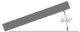 |
|
| |
|
Horizon angleHorizon angle is separated from horizon angles for the building and has only one value in the direction of the solar collector. |
|
Water heating distribution |
|
Restriction of heating capacity The function is used in order to limit available power for heat supply. The restriction of power is supervising requirements concerning room temperature and supply air temperature and heat needed for hot tap water. The function gives an increased possibility for calculating buildings with a restricted access for power which means that the desired room temperature is not achieved. The calculation is executed in the following stages. 1. The user states the maximum available power from the heat maintenance 2. The software completes with available power from solar collector, heat pump and heat exchange from the exhaust air. 3. The software calculates necessary heating power with set points for room temperature and supply air temperature but if the available heat is not enough then the resultant room temperature is calculated. 4. The restriction of power does not cover an additional power for heating of supply air that sometimes is a consequence of the VAV system function. 5. Any remaining power from heat maintenance is used for hot tap water. Priority order for use of available heat: 1. Supply air 2. Underfloor heating 3. Other room heat 4. Hot tap water Underfloor heating is prioritized before other types of room heat since the need for underfloor heat temperature normally is lower than that of other types of room heaters. |
|
| |
|
Electric power circulation pumps The electric power to the circulation pumps will be distributed by the water heating system. The two values for power to circulation pump will be added in the calculation. The pump is running as long as there is a heating demand. |
|
| |
|
Water temperatures in heating system The temperature in water heating system can be controlled via outdoor temperature or room temperature. By controlling via outdoor temperature supply and drain temperature are controlled via outdoor temperature. By controlling via room temperature supply and drain temperature is controlled via power demand. The water flow is controlled by power demand and difference between supply and drain temperature. |
|
| |
|
Heat demand covered by water heating Share of heating demand for room heating, except demand covered by underfloor heating, covered by water heating. The rest of the heaters can for example be electric heaters or fireplaces. If all heaters are connected to water heating system the value is 100 % regardless of underfloor heating share. |
|
| |
|
Heat pump Several heat pump units (compressors) can be connected to the water heating system. In case of several heat pump compressors they are parallel coupled to the water heating system. The total water flow has to be divided to the compressors. Normally the water share is proportional to output power. Heat pumps of the type Air/Air is treated separately and can work in the demand space that uncovered by the water heating system. The system can be complemented with a accumulator tank that can be connected serial or parallel to the heat pump units. The control of minimum time for operation and truce is normally 10-20 minutes. |
|
| |
|
Hot tap water |
|
| |
|
Consumption Heat demand for hot tap water is given in operation case catalog as W/ m2 floor area. |
|
| |
|
Heat recovery Heat can be recovered from waste water or other source. The consumption of hot-water is given as power per m2 floor area. The user states if any equipment has been installed to recover energy out of wastewater for pre-heating of hot water. The efficiency depends on how big share of the hot-water need that is covered by the recovery system. |
|
| |
|
Temperatures Temperatures at cold and hot tap water are used for calculation of heat recovery from solar collectors and heat pumps. |
|
| |
|
Energy efficiency If equipment for heat exchange of heat from waste water to hot-water is installed, the efficiency is specified here. Normally the efficiency is 20-30 %. |
|
Heat release from piping systems for hot tap water and water heating system Internal heat release is calculated on the difference between the temperature of hot tap water and indoor temperature. The temperature of the recirculation pipe is assumed to be the same as in the hot water supply. External heat release is calculated against a ground temperature of normal laying depth for heat culverts 0.5 m. Heat release from circular single pipes can be superannuated according to the following formula. Internal and external transition resistance is ignored, giving an extra margin. For co-insulated double tubes, the calculation is more complicated, but as a rough estimate you can add internal diameter for the two tubes. A more accurate calculation can be made with 2D calculation in VIP-Energy. Pipes and insulation are best simulated as squares with the same circumference as pipes and insulation. P=2*pi*λ/ln(de/di) P: Heat release W/mK λ: Thermal conductivity W/mK de: External diameter di: Internal diameter pi: 3,14 Example: λ=0,04 W/mK
dy/di |
P W/m,K |
2 |
0,36 |
3 |
0,23 |
4 |
0,18 |
5 |
0,16 |
6 |
0,14 |
8 |
0,12 |
10 |
0,11 |
Heat release from factory-made culvert can be retrieved from data sheets. Sometimes heat release is indicated as W/m at a certain temperature difference. Divide the energy emitted by the specified temperature difference before input to VIP-Energy. Heat to room air A proportion of the heat from used hot tap water can be emitted to room air. For percentages see further in publications from Sveby.org or the Swedish National Board of Housing, Building and Planning. Electric heat Heat supply marked as EL heat can be replaced by solar electricity. Control losses The program takes into account regulation losses through a supplement at room temperature. Regulation losses are due to deficiencies in heat regulation that may result in a slightly higher room temperature than the lowest allowed. Minimum permissible relative humidity The program increases the relative humidity of the room air by steam humidification. The energy consumption of the humidification is reported separately in printouts. |
|
|
|
Cool supply |
|
 |
|
|
| |
|
Generic The user can choose passive cooling, cooling machine connected to water cooling system or district cooling. In validation mode DX-cooling machine operating on room air or supply air is added. |
|
| |
|
Passive cooling Passive cooling takes no energy consumption. Otherwise it works as district cooling. |
|
| |
|
Cooling machine water cooling system There is an option to put in two operating points which the program interpolates between. |
|
 |
|
| |
|
COP cooling The relation between cooling power and supplied electric power. The value is used for calculating the electric consumption in cooling machines. |
|
| |
|
Limit for free cooling For outdoor temperature under that limit there is no energy calculated for the cooling machine just for the circulation pump. |
|
| |
|
Cooling machine DX-cooling(Only validation mode) In corresponding catalog input for that type of cooling machine can be specified. |
|
| |
|
District cooling Cooling from external supplier. Calculated cooling comprises sensible (thermal) energy latent energy (condense). |
|
| |
|
Power to circulation pumps The program calculates the electric power to circulation pumps as a part of the cooling that is distributed by the cooling system. |
|
| |
|
Maximum RH in room air Reducing RH to maximum relative humidity will cause latent cooling energy. Normal value is 75 %. |
|
| |
|
Cooling recovery for VAV forced exhaust air If the function is activated cooling is recovered if VAV exhaust air temperature is lower than outdoor temperature. |
|
| |
|
Restriction of cooling capacity The restriction of available cooling power is superior to demands for room temperature and supply air temperature. The room temperature can exceed the in Operation Case given limitations if the cooling power is restricted. The order of priority for use of available power. 1. Supply air 2. Room cooling 3. Forcing VAV flows |
|
| |
|
|
|
Economy |
|
 |
|
| |
|
Generic The Economy menu opens input for the choice of energy prices. The input is similar to operation cases. Choices of predefined price combinations can be done with the energy price catalog commanding button. A dialog box from which a choice can be done is shown. Every hour of the year must be covered in the time specification to get the total cost calculation. Green marking indicates that input data are OK. Dark green hour is covered by time specification and light green is covered by prices that are valid by remaining time function. Yellow indicates missing data and red multiple data. |
|
| |
|
Time schedules Hours and price labels are stored in time schedules stored as catalog data available for all projects. All time schedules are available under Operation, Economy and time controlled ventilation. |
|
| |
|
Remaining time Remaining time covers hours that are not specified in the time table. |
|
| |
|
Energy prices Energy prices are specified in separate catalog. |
|
| |
|
Hours and weeks Start time and and stop time must be in the same day and start time must be lower than stop time. It is valid for current weekday from start week to stop week. |
|
| |
|
Date function It is used to translate date to week number 1-53. |
|
| |
|
Copy function Input data can be copied between week days. Once copy function from one day to another is activated, copied data is always updated. |
|
| |
|
Restrictions:
Value: |
Min: |
Max: |
Start week: |
>=1 |
End week |
End week |
>Start week |
<=53 |
Start time: |
>=0 |
End time |
End time |
>Start time |
<=24 |
|
|
|
|
Demands according to Ashrae 90.1 and LEED |
|
 |
|
GeneralThe dialog contains the features required for making a comparative calculation according to Ashrae 90.1 Appendix G. It is the basis for the assessment of energy efficiency in buildings according to LEED. The calculation deals with two project files that both created manually in advance by the user. This function carries out calculations of project files and reports the results. Proposed BuildingThe Proposed Building file contains data for the real building. The file can be a calculation with a zone or the master file for a calculation with multiple zones. With the file, the program performs a calculation in the same way as during a typical calculation. Baseline Building File with Baseline Building contains data for a building with essentially the same architecture as Proposed but with specific properties. The user creates the file in the same way as a normal calculation. The program implements 4 calculations with Baseline Building and calculates the overall result. For every calculation the building is turned 90 degrees. Single/Multi zoneWhen files are opened and loaded the program register if they contain multiple zone or one zone and select the radio button. Even if the file contains multiple zones, the user has the option to choose to calculate it as single zone. Edit filesThe buttons give access to a dialog where individual zones in a file with multiple zones can be edited. It's basically the same function that are in the dialog for calculation with multiple zones. Calculate Proposed and Baseline BuildingWith the button starts the calculations and results are stored internal in the program. |
|
Solar cells Exposure and orientation of solar cells |
|
 |
|
GeneralThe dialogue is used to build a plant with individual solar cells. Different types of solar cells can be combined and oriented optional. Each individual solar cell can be given an individual shading. DescriptionText fields that optional can be used to describe a single record with solar cells. Solar cell typesSolar cell types is obtained from separate catalog containing the specification of properties. OrientationEach entry can be oriented free to 8 points of the compass as well as horizontally. RotationEach entry of cells can be rotated any number of degrees with reference to the given point of the compass. TiltEach entry of cells oriented in any point of the compass can be tilted upwards from a horizontal position. With orientation "roof" slope is 0 degrees. ShadingDescription of shading will be downloaded from separate catalog. Battery capacityThe plant can be equipped with a battery capacity which can store a certain amount of energy. The capacity is expressed as Wh per solar cell area. Battery efficiencyBattery efficiency indicates how much energy can be obtained from the battery in relation to the amount of added. Equipment efficiencyThe value refers to the efficiency of the frequency transformation and other equipment that is not affected by solar cell temperature. The efficiency affect all produced solar electricity. |
|
Share of solar power |
|
The input dialog gives the user the opportunity to control how solar electricity should be used. There is an opportunity to prioritize consumers in an order from 1-8. Priority 1 is assigned in the first place and priority 8 in the last. If several consumers are given the same priority, solar electricity is distributed in relation to total electricity needs. That distribution is updated hourly. In zones, it is possible to distribute electricity to all users, however, electric heating must be ticked in the heat supply dialogue for the choices for electric heating to be active. Solar electricity produced in supply centers can be used internally within the central but is limited to heat pumps, chillers and fans, pumps. However, this limitation is not highlighted in the dialogue. The distribution specified in the central specifies how solar electricity is to be distributed to consumers within a single central. |
|
Shading of solar cells |
|
 |
|
GeneralWith dialog, you define the shading of solar cells with the help of two screens that can be rotated horizontally and two vertically. All 4 screens can be placed optionally in the distance, the transverse and vertical relative to the solar cell. The placement takes place in a 3D coordinate system in which the solar cell's bottom is the x axis. Z-coordinate is the distance from the solar cell and the Y coordinate height over the solar cell bottom Each screen can be activated individually. Panel dimensionsSolar cell's width and height are a prerequisite for the estimation of shading. |
|
| Calculate |
|
 |
|
The menu is used for starting a single zone calculation. All inputs must be defined and approved to start a calculation. The user can choose Calculation period, for example the month of October, by putting Start day to 274 and End day to 304. It is elective within the interval 1-365 days. When the calculation starts the horizontal staple will show how the calculation goes on. In the list box information is shown about the calculation and if some problem occurs:
Value: |
Min: |
Max: |
|
Start day: |
>=1 |
End day |
|
End day: |
>Start day |
<=365 |
|
|
|
|
|
Multiple zone calculation |
|
 |
|
| |
|
Generic With zone calculation the user can calculate connecting zones and get the resulting energy consumption for a whole project. The zones can be connected to common supply centrals which can hold heat pumps, solar collectors and information about constrained capacity for heating and cooling. The calculation starts when pressing the Calculate button. The result can be seen through the Result menu choice. The user can print out the result by File / Preview/Print the menu choice. |
|
| |
|
Initiation of supply centrals Right button click at the list for supply centrals, add an item and give it a name. Connect a file to the central item. |
|
| |
|
Initiation of zones Right button click at the list for zones, add an item and give it a name. Connect a file to the zone item. |
|
| |
|
Connecting supply centrals to zones A zone can be connected to a energy source in a supply central. The combination of connection to sources in different central is optional. |
|
| |
|
Validation mode The priority order for the cone in the central can be set which specifies in which order energy will be allocated to the zones that are connected to the specific energy source. It is even possible to specify if the local energy source in the zone or the common source will be used in the first hand. |
|
 |
|
Connecting zones Two zones can be connected by stating their name, the building part that forms the boundary between the zones and the area of the boundary. Only building parts from the 1 dimensional building part catalog can be used as zone boundaries. These building types are listed in the Building Type list box. The file that is open in the software´s main window do not have to be a part of the zone calculation ,but building parts for zone boundaries are taken from that file. To connect zones is optional. All zones in the zone list are calculated even if not connected to other zones. |
|
| |
|
Air temperature an moist transmission between zones The input box "Share of air from zone B to zone A" indicates the proportion of outdoor air or extract air to ventilation units to be taken from the opposite zone. Air can be mixed from any other zone up to 100%. The remaining proportion up to 100 % is taken from outdoor air if the air mixture is taken in as outdoor air to the unit and as the air of the own zone if the mixture is taken in as extract air. Under the dialog “Control case” for each unit, it is free to choose whether to bring outdoor air or exhaust air from this air mixture. |
|
| |
|
Common folder It means that it is assumed that all zone files is located in the same folder as the master file. |
|
| |
|
Use catalog data from master file in all zones If checked catalog data from master file is copied down to zones. Copies is made of catalog objects that exist in both master file and zone file. The master file do not crate new objects. |
|
| |
|
Calculation The calculation is initiated when pressing “Calculate”. The program indicates that there is a calculation in progress by writing a relative imbalance for the energy flows, the number of iterations and the currently calculated zone. The iteration is discontinued when the relative imbalance for energy flows is less than 0.1%. The calculation can be interrupted by clicking "Calculate" again. The program then asks a question whether the calculation should be interrupted where you can answer yes or no. |
|
| |
|
Results |
|
 |
|
| |
|
Generic The Result menu is used for showing the result of the calculation directly. The menu alternatives under Result will be active when when a calculation, single or multi zone, is performed. The result choice is inactivated when any input data, relevant for the calculation, is changed. |
|
| |
|
Energy map |
|

|
|
The energy map is the base for presentation of results where the energy flows is defined with a label and a number. |
|
| |
|
Time detailed energy balance |
|
 |
|
| |
|
The result will show as a table, and different energy types will be shown. The period result is the total result of the months. If Week is chosen as result account, only the weeks the user has calculated are shown. With the Day alternative the user can tell exactly what days are to be shown in the table (the text boxes Start day and End day) in the calculated interval and the period result will show the total result for the days in the table. At Hour presentation the user can only see the result of one day at a time. Choose a day in the Day text box. The period result shows the result of the day. |
|
| |
|
Key Values |
|
 |
|
Some key values that can be useful in result analyze are presented. Internal heat capacity is the part of the heat capacity that is in contact with room air. Outer heat capacity is in contact with outside air and is reducing temperature variations trough the wall. The average room temperature is the lowest allowed temperature specified in operating cases. This is also the average temperature during hours with supplied heating energy. During the whole calculating period the average room temperature is higher than this value. Infiltration at 50 Pa is the sum of the leakage points of the building included fresh air valves in to the building. Inside air pressure is the average pressure at the level 0. Difference low and high room temp intends difference between calculated room temperature and prescribed in operation case. It shows up in case of restriction in available power for heating and cooling. The VAV-value is the share of total cooling energy that can be supplied by the VAV-system. |
|
Energy balance |
|
 |
|
The values in this window are the calculated period summary results. They are presented as a energy balance with emitted energy at the top and supplied energy at the bottom. The balance includes virtually energy passing the building envelope. External activity and operating energy is left out. |
|
Specification of energy supply |
|
 |
|
The table presents a detailed energy specification supplied to the building. It is possible to show monthly or yearly values. |
|
| |
|
Economy |
|
 |
|
This window shows the energy cost for the whole calculation period. The energy cost is calculated in connection with calculation of energy consumption for heating. The energy cost is divided into the following items: Heating of room, supply air and hot-water except electric heat. Process energy Electric energy for el motors as fans and pumps. District cooling Material cost is calculated from energy price, density and weight specified in the material catalog. |
|
|
|
Report generator |
|
 |
|
Select the predefined reports. |
|
| |
|
| |
|
Value export to text file |
|
 |
|
The dialog is used for specifying values for export to a text file. The values are exported to an optional file name. For multi zone calculation values for each zone can be exported. |
|
| |
|
Graphical record The result can be presented graphically in either a pie diagram or in a time diagram. In the time diagram the user will choose values for hour, day, week or month. The user chooses the values and the colors of the graphical record. |
|
| |
|
Pie chart supplied energy |
|
 |
|
| |
|
Pie chart emitted energy |
|
 |
|
| |
|
Bar chart energy balance |
|
 |
|
| |
|
Bar chart duration diagram |
|
 |
|
| |
|
Room temperatures |
|
 |
|
Exhaust temperature  |
|
Multi zone calculation |
|
 |
|
In case of multi zone calculation result windows holds a drop list with zone names and the specific result for each zone can be chosen. |
|
| |
|
| Top of page |
|
| |
|
Printing |
|
Printing options It is possible for the user to customize the printout by selecting the “Printer options...” entry in the “File” menu. Contents and colors of specific results can be specified in an intuitive way. |
|
 |
|
At zone calculation printing selection is chosen for every single zone file. In the master file you can choose to view results and in data in general. |
|
 |
|
| Top of page |
|
| |
|
6. Calculation methods There are several calculation models included in VIP-Energy. The model for heat storage in the building structure is described in [1]. The model for calculation of air flows through the ventilation systems and air infiltration through building parts is described in [2]. There are also calculation models for solar radiation through windows, heat pumps, solar collectors etc. There are two intersections where the properties of the included systems are meeting. One intersection is the inner air pressure of the building. There are wind pressure, thermal, leakages and ventilation flows meeting in an air system, with balance between supplied and exhausted air. All the factors have a mutual connection. The other intersection is the temperature of the building frame. There the energy flows for sun, processes, ventilation, infiltration, transmission etc. are connected in an energy system with a balance between supplied-, emitted- and stored energy. The program contains also calculation models for 2- and 3-dimensional heat flow. The models is built on finite difference methods. A iteration calculation is performed until energy balance is achieved in single nodes and in the entire model. |
|
| |
|
6.1. Time division The program is built on a dynamic calculation model, which means that the calculation is repeated hour per hour during the entire calculation period which can amount to a whole year. Energy flows and temperature is calculated considering the influence of climate factors such as outdoor temperature, relative humidity, sun and wind. Various demands on room temperature and air exchange control the calculation. |
|
| |
|
6.2. Single zone model The program contains a single zone model. This means that the calculation result best agrees with buildings that contains a homogeneous activity with similar temperature demands. If the building contains different zones with separate temperature demands then each zone should be calculated separately even though the coherent energy consumption is calculated by a group calculation. The user must, before the calculation starts, take consideration to if the building contains partition walls or slabs that are essentially tighter than the outer casing of the building. Office buildings and homes usually work as coherent air cells and the whole building is described as a coherent volume. |
|
| |
|
6.3. Inherent heating systems The program contains a function for simulating inherent heating systems of the types under floor heating and roof heating. The user specifies where in the construction the heat layer is and how big share of the total needed power for room heating that should be given from each floor, wall or roof surface. The program calculates the needed temperature in the heat layer and the heat storage that gets the result of the temperature raise. If the building part is located in the climate shell, the increase of the transmission that gets the result of the raised temperature is calculated. If the building part is an inner area then the energy consumption can only be affected by heat storage at a time when there is a need for heat and if the stored heat is wasted at a later time when there is a surplus of heat. The program does not take into consideration if the calculated temperature is on a reasonably level. It only takes into consideration if the building part delivers necessary power to keep the set point for room temperature. The increase of transmission is used for adjusting the U-value of the building. |
|
| |
|
6.4. Solar heating systems The program simulates the function of a solar collector connected to an accumulator tank. The user specifies the size and performance of the solar collector and the volume and temperature limits of the accumulator tank. Every hour of collected solar energy and temperature of the accumulator tank is calculated. The user can specify what the solar energy will be used for and energy will be given if the temperature is above the lowest temperature limit. |
|
| |
|
The figure shows a solar heating system with collector, accumulator tank heating system and hot water system. The accumulator tank is only used for storing heat from solar collector. |
|
| |
|
6.5. Heat pump |
|
| |
|
6.5.1. Default values I order to minimize input data, default values has been set as far as possible. Data about compressor function dimensioning of heat exchangers in evaporators and condensers and other data that normally do not exist in data sheets or other information from suppliers has been set to standard values. 6.5.2. Compressor function The calculation function proceeds from how compressor performance is influenced by condenser and evaporator temperatures. Data for this has been collected from special software for simulation of compressor function. Each refrigerant type has its own characterization. The 3D diagrams shows the principle for the balance between evaporator energy and condenser energy in a exhaust air heat pump. Condenser power and evaporator power is both depending on evaporator temperature Te and condenser temperature Tc. The power of the heating system is depending on condenser temperature and the heat source power is depending on evaporator temperature. There is always a combination of Tc and Te where there is a balance between the power of evaporator and condenser, the heating system and the heat source. |
 |
|
Basic data for heat pumps is collected from data sheets. It usually contains output power compressor power, refrigerant and other data needed for VIP-energy. Data is for one condenser temperature and one evaporator temperature. The shape of the diagram is depending on the refrigerant. The user choose type of heat pump depending on heat source and where ti deliver the heat, water system or room air. |
|
| |
|
6.5.3. Heat exchangers Evaporator and condenser is two heat exchangers that transfer heat from brine and heating system to the refrigerant. The heat of transfer is chosen to a value so the temperature gap is 5 °C at nominal heat power. Nominal power is assumed to occur at evaporator temperature 0 °C and condenser temperature 45 °C. In the calculation current flows and temperatures is used to calculate condenser and evaporator temperatures. The function follows natural logarithm relationship. |
|
| |
|
6.5.4. Testing standards Input data contains information about which standard is used for the heat pump test. Test data is more favourable at testing according the older standards EN 255 than EN 14511. In VIP-energy its assumed that the temperature gap between supply and drain temperature is 20 °C when testing according EN 255 and 5 °C when EN 14511 is used. For heat pumps bringing heat from brine or outdoor air temperature is used as cold side reference. For exhaust air heat pumps exhaust air flow is used as reference. Exhaust temperature is 20 °C and relative humidity 40 % according to test standards. |
|
| |
|
6.5.5. Hot gas exchanger Close after the compressor the refrigerant gas is warmer than the condenser temperature and the temperature difference can be used to produce hot water at a higher temperature than heating system temperature. |
 |
|
| |
|
6.5.6. Energy sources Heat an be regained from outdoor air, exhaust air, sea water or ground sources. VIP-Energy calculate the heat source temperature depending on evaporator power and climate according to an ordinary design. |
|
| |
|
6.5.6.1. Geothermal (Rock) For wells in rock it is assumed that a balance temperature normally occur after some years of operation. The balance temperature will bee some degrees under the year average of the outdoor temperature. A temperature gap between the well and brine is calculated considering speed and relative evaporator power. |
|
| |
|
6.5.6.2. Exhaust air For exhaust air heat pumps discharge air temperature is calculated considering exhaust air temperature, flow rate and moist content. Condensation of moist is not trifling at recovery from exhaust air. Input data has been completed with information about moist addition to room air as moist per floor area and time unit. When discharge air temperature goes under zero there will form ice in the cooling coil. The amount of ice is calculated and defrosting is performed by stopping the heat pump during necessary time. The defrost temperature has been chosen to +5 °C and which means that the energy content in exhaust air during the defrost time is supposed to be the same as the need to melt the ice with a margin of 5 °C. In case of speed controlled compressor the power is increased to cover the energy need during the defrost time. In case of constant speed has defrosting an impact on available operation time but not on evaporation and condenser temperatures. |
|
| |
|
6.5.6.3. Ground source heat pump soil collector The heat source temperature is calculated with time displacement and compression of outdoor temperature corresponding to 2 m soil deep and some degrees temperature lowering. |
|
| |
|
6.5.6.4. Sea collector The heat source temperature is calculated in the same way as soil collector except that the temperature don´t goes under zero. |
|
| |
|
6.5.6.5. Outdoor air coils The evaporator temperature is calculated directly to the outdoor temperature. In case of evaporator temperature below zero icing in the coil is calculated. Temperature lowering in the coil is assumed to 5 °C. Energy is used to melt the ice and put up the temperature some degreed over zero. In the combination of outdoor collector and water heating system the energy loss for circulation to protect freezing. It is done when in case of outdoor located compressor and freezing risk in the water heating system. The user input is specific power demand and the energy loss is calculated between system and outdoor temperatures. If there is a accumulator tank energy loss is calculated if out door temperature is below +2 °C or if the compressor is operating. Is there no accumulator tank energy loss is calculated continuously. If the compressor is operating the energy loss is covered by recovered heat. In other case it is all covered from the external heat supply. |
|
| |
|
6.5.7. Heat distribution Heat pumps can give off condenser heat to water heating system hot water system. Air/air heat pump can give off heat only to room air. |
|
| |
|
6.5.7.1. Water heating system The user gives temperatures in water heating system an if the heat will be controlled to power demand or to outdoor temperature. The user gives also priority order for water heating system and hot water system. In input windows for building parts and in control catalog for ventilation units there is check boxes to decide if the component should be heated by water heating system or in other way. In input window for heating and cooling the user can decide how big share of radiators that is feed by the water heating system. Depending of choice of control method temperatures in water heating system is calculated from power demand or outdoor temperature. When choosing control depending on outdoor temperature floor heating, ventilation units and radiators are shut off at decreasing power demand. That is more probable than a parallel reduction of flow in all units. Current supply temperature is calculated from nominal drain temperature and the temperature raise depending on the condenser power. The drain temperature of the heating system is in the reality limited downwards by the room temperature and to avoid numerical problems in calculation it is limited at room temperature + 2 °C. The temperature raise in the condenser is established in the moment at compressor start. If the the supply temperature exceeds nominal value the distribution capacity of the heating system also is exceeded and even the drain temperature will raise to a higher value. How fast that happens is depending on active water volume. System volume has assumed to 7 liter per kW power with system temperatures 55/44 °C. The same value is used for radiators and underfloor heating. The user decide the shortest allowed operation/truce time. If the condenser temperature during operating time exceeds maximum allowed temperature the heat pump stops during the rest o the hour. |
|
| |
|
6.5.7.2. Air heating Air/Air heat pumps is treated separately. These can deliver energy for demand not covered by water heating system through radiators, ventilation or under floor heating. |
|
| |
|
6.5.8. Accumulator tanks The user can increase the temperature stability in the water heating system by adding accumulator tank. If serial connected to the heat pump it has no influence on the water flow. It just stabilize the drain temperature. I parallel connected the compressor always work with a constant optimal flow and a temperature raise of 7 K |
|
 |
|
The Figures shows the difference between parallel and serial connected tank. |
|
| |
|
6.5.8.1. Sequence control The user can add more than one heat pump units (compressors) that starts in sequence depending on power demand for heating system and hot water. The figure shows a plant with two heat pumps with two compressors in each heat pump. In reality it looks like two heat pumps but in VIP-Energy it is described as four heat pump units of which three only works to heating system and one even works to hot water system. |
|
 |
|
| |
|
6.6. Energy balance The figure below shows the energy flows that are calculated in VIP-Energy. |
|
 |
|
| |
|
6.6.1. Heating/cooling The user states, for every hour, a minimum and a maximum value for the room temperature that cannot be exceeded at any direction. Room temperature means the average air temperature of the building. A lowest allowed value for the temperature of the supply air will also be given for the whole year. Energy is needed for reaching the minimum temperature in room air and supply air and also to manage hot-water heating. If the room temperature tends to exceed the pre-installed max-value, an extra energy quantity will be emitted. These energy quantities are mentioned as heating or cooling energy. Cooling energy does in this case mean not only active chilled energy, but chilling can also mean extra airing. Except for the quantity of cooling energy, the maximum temperature will affect the using of the building’s heat capacity, through a limit of the swinging amplitude of the room temperature The electric energy that is used by heat pump, circulation pumps and fans, is added to the sum of heating energy. |
|
| |
|
6.6.1.1. Heating Energy for heating is supplied to the building as: Heating in purpose of keeping the room temperature above the lowest allowed value; can in most cases be called radiator energy. Heating of supply air in purpose of keeping the supply air temperature above the lowest allowed value. Heating of hot-water. The energy access is the same as for given energy hot-water. Electric energy is needed for heat recovery with the help of a heat pump or extra fans. This electric energy is also included in the sum for heating. |
|
| |
|
6.6.1.2. Cooling Energy consumption for cooling of the building consists of: Electric energy to a cooling machine which is counted as a factor of needed cooling power. Condensing losses at moisture reduction of supply air. If cooling the outdoor air the user will under normal circumstances (when temperature and moister approaches the dew point) get a condensation of water that demands an increasing cooling power. |
|
| |
|
6.7. Air system Air infiltration through the climate shell of the building is calculated considering differences of pressure over the shell. Pressure is affected by unbalance between supply- and exhaust air flows in ventilation systems, thermal pressure due to density differences between inner and outdoor air and wind pressure. The permeability can vary for each building part. |
|
| |
|
6.7.1. Air infiltration |
|
 |
|
An air infiltration calculation follows a method described in [1]. Air flow through an outer area is supposed to follow the function Q=infiltration flow K=Flow coefficient [?]. A=the building part area [m2]. dP=Pressure difference [Pa] ß=Flow exponent. 0.5<ß<1.0 is depending on the degree of turbulence in the air flow. The value 0, 5 indicates total turbulent flow and 1 indicates total laminar flow. The program puts the flow exponent to a normal value of 0, 65 for every area. The relation between pressure and flow is not always linear, which means that affected pressure over a building part cannot be summed. An inner equilibrium pressure is calculated so that in and out coming airflows are equal. Equilibrium pressure is calculated in a fitting calculation. Flows in fan directed ventilation systems are not affected by inner air pressure in the calculation but are supposed to be adjusted considering inner pressure. The flow that passes out through the buildings climate shell is defined as infiltration. The inner air pressure and the outside pressure affect the air infiltration. The permeability of building parts are indicated with a q50-value. q50 indicates the infiltration per square meter at 50Pa pressure difference. |
|
| |
|
6.7.2. Ventilation systems If exhaust- and supply air flows are given the same values, the ventilation system will function as an exhaust and supply air system. If no value of supply air is given, it will function as an exhaust air system, but all variations between them can exist. The user can also give a larger value for the supply air than for the exhaust air. Any permanent terms on different types of systems do not exist in VIP-Energy. A so called FTX-system will be simulated if a heat exchanger gets efficiency. In an exhaust air system it is assumed that supply air valves take in the air. These valves are in VIP-Energy represented by extra leakage against the outdoor air. The performance of the valves is described in VIP-Energy as flow at a pressure fall of 50Pa (q50). Appendix 5 shows data for some types of supply air valves. In the cases where the diagram does not go as far as to 50Pa the value can be extrapolated from some other pressure fall, for example 20Pa. For this the following relationship is used: |
|
 |
|
For supply air the flow exponent is (ß) 0.5. The energy consumption is calculated out of the efficiency of the fans, fan pressure and flow. The electric consumption of the fans is calculated with the formula: |
|
 |
|
P=power, W ŋ=efficiency q=air flow, l/s dP=fan pressure Pa The electric consumption of the exhaust air fan is supposed not to utilize the building while energy of the supply air fan is brought back to the building. |
|
6.7.3. Energy recovery The energy efficiency of the current building, which is given as input to VIP-Energy, is the energy efficiency of the recovery systems with consideration to temperature losses from the duct system. Formulas for calculation of energy efficiency are in a special appendix. The exhaust air flow and temperature together with outdoor temperature and heating need are included in the calculations for recovered energy. |
|
Heat exchanger General VIP-Energy includes simulation models for the most common types of heat exchangers. Initially, the program creates a computational model of the exchanger with test data according to EN308. Test data must contain efficiency and associated test flow that should be equal for supply air and exhaust air. Testing according to EN308 takes place without condensation or icing. The program calculates the hourly heat recovery, condensation, icing and defrosting and moisture recycling in the light of current conditions. |
|
| |
|
| Plate heat exchangers |
|
 |
|
In the plate heat exchangers are flows entirely separated with a thin sheet which transmits heat. Maximum efficiency is achieved if flows oriented counterflow. See illustratuion above. |
|
 |
|
| It is in manufactureing easier to orientate the flows of 90 degrees to each other. It is called cross-flow exchanger. (Above) To increase the efficiency, you can add two cross-flow exchanger in series. |
|
| Rotating exchanger |
|
 |
|
An air permeable metal rotor transfers heat between the two flows. Both flows come in contact with the same material surface and thus can even moisture and other substances be transferred. |
|
| Heat storage package exchanger |
|
 |
|
| In a Heat storage package exchanger switching air flow direction with certain intervals. Metal plates in air flow transfers heat but also moisture and other substances. |
|
| Run-around coil exchanger |
|
 |
|
| Air flows are separated and heat is tranfered with a fluid between exchange batteries. The fluid is usually a glycol solution. |
|
| Defrosting methods |
|
In the plate heat exchangers and Run-around coil exchanger there can be problems with icing. If there is a moisture addition in indoor air condenses the moisture in the changer if the outside temperature is low enough. When the outside temperature is considerably below zero, the condensing water congeal that stops up the flow and reduces heat transfer. In cross-flow exchanger and run-around coil exchanger the software takes into account the fact that the temperature distribution in the warm flow is uneven and that the icing begins in a corner to be spread out over the changer surface. |
|
Demand-controlled defrosting Efficiency is reduced periodically by the cold air flow is by-passed the changer or by the liquid flow is reduced. The heat in the hot air flow melts away the ice. There may be variations in how effective defrosting is done and there is an option to add a margin of safety in addition to the optimal needed time that is calculated in the software. |
|
Limitation of exhaust air temperature The efficiency is reduced continuously by a certain part of the cold flow is released by-past the exchanger or the liquid flow is reduced. Warm flow out from the exchanger is over a certain temperature a few degrees above freezing. The temperature is measured in the airflow but the plate surface is slightly cooler. |
|
Preheating of the outdoor air A electric coil in the outdoor lifts air temperature before the changer enough to avoid icing. It may be sufficient to raise the temperature to a few degrees below zero when the plate surface has a higher temperature. |
|
Time controlled defrosting Under certain out door temperature, usually a few degrees below zero, efficiency is occasionally reduced with certain intervals by cold flow bypassing the exchanger or by the liquid flow is stopped. The percentage indicates the percentage of time that the changer is on defrost. |
|
Number of sections When the exchanger is defrosted through the by-pass of the whole cold air flow transfers the whole power of heating of outdoor air to heating coil. If the heat exchanger is divided in two halves power requirements for heating coil. Theoretically number of sections by the time necessary for defrosting. If it needs 6 minutes defrost per hour, it is not possible to use more than 10 sections. The program maximizes the number of use sections, taking into account the calculated defrosting time. |
|
| |
|
6.7.4. VAV-system Forced air flow at cooling demand |
|
 |
|
Principal construction of ventilation unit |
|
| |
|
6.7.4.1. General The VAV-function works with the cooling demand that is calculated according to highest allowed room temperature. Data for VAV-flow I separated from other ventilation data. The VAV-function can only be used in combination with cooling machine or district cooling. You can choose between two control principles, prioritize cooling of supply air or forced air flow. At passive forced air flow is air flow increased without any cooling supply. VAV-cooling is presented separately and in that post is all colling supplied to time controlled and temperature controlled ventilation included. The cooling demand can be covered up to a power limited by lowest supply temperature and maximum air flow. Cooling demand that can not be covered is presented as cooling in room air. The increase of flow is always the same for exhaust and supply air and is limited by the smallest gap between maximum allowed flow an current time controlled flow for all temperature controlled units. |
|
| |
|
6.7.4.2. Priority of cooling In firs place time controlled supply air temperature in lowered to minimum level for VAV-cooling. First the recovery is lowered then cooling is added. In second place the air flow is increased up to maximum level. |
|
| |
|
6.7.4.3. Priority of forced air flow In first place supply air temperature is lowered as far as possible by reducing recovery and heat supply. In second place air flow is increased to maximum maximum allowed. In third place cooling is added and temperature is lowered to minimum level for VAVcooling. |
|
| |
|
6.7.4.4. Condensation The supply air is dried to maximum allowed relative humidity for room air and maximum 100 % in supply air at cooling coil. The supply fan is situated after the cooling coil so the air in coil is a bit lower than stated supply temperature. |
|
| |
|
6.7.4.5. Limit of available power When affect for heating and colling is limited the VAV-function has last priority. The VAV-flow is limited depending on available power. |
|
| |
|
6.7.4.6. Recovery Recovery of cooling is in standard tables presented as increased ventilation. In the export function to text files cool recovery can be separated. |
|
| |
|
6.8. Heat capacity The allowed span for the room temperature affects the use of the heat capacity of the building. It’s up to the user to choose values, but for offices and homes etc. temperatures out of the +20C-27C span should not be allowed without special explanation. The calculation of active heat capacity follows a method described in [2]. The homogeneous heat capacity of the building parts are concentrated in the model to layers separated by heat resistances. The model is analogous with the electric science, where resistance corresponds to heat resistance and condenser to heat capacity. The calculations in the program are done with inner and external heat capacity (C1 and C2 in figure 1) and three thermal resistances (R1, R2 and R3). C1 and C2 represent the part of the heat capacity of the wall that contributes in the exchange of energy with the surroundings. R1 represent the heat resistance between the inner heat capacity and the inner air and R3 between the external heat capacity and the outdoor air. R2 is the remaining heat resistant. The calculations of the values of the components are done with a starting point from the differential equation for stationary heat flow. |
|
 |
|
Figure 1 The heat flow equation says that “the temperature change in a point is proportional to the temperature curve bending in the point, proportional to the heat flow number and conversely proportional to the specific heat capacity”. There are connections between temperature and energy flows at the limit surfaces of the building part. The equation can only be solved under the condition that the temperature is changed with harmonic swing movements with a certain period length. The period length has been settled to 24 hours in the program. This period length has been chosen because the biggest energy quantity towards and from the heat capacity as a rule has a turnover due to the 24-hour variation of the temperature. Figure 2 show limits for the swinging amplitudes in a homogenous wall and in the calculation model. |
|
| |
|
 |
|
Figure 2 The values of the component C1, C2, R1, R2 and R3 are calculated so that the energy flows through R1 and R3 in the model are exactly equal in size to the real energy transport towards and from the limit surface of the building part on the in and outside. This is under condition that the external temperature variations have a period length of 24 hours. Figure 2 describes a homogeneous wall but the model is used for an unlimited number of levels. In the program the number of levels is limited to a maximum of 50. All the building parts are translated to models according to figure 1. These models are consolidated to one model with similar features and with this sum model (which represents the whole building) the energy calculations are done hour by hour. The model describes the heat storing function for the whole building. The calculations are done with a balanced mean value for the inner temperature of the building and a corresponding value for the outdoor temperature. A value that considers the outdoor air temperature and the temperature increase on the surface of the façade through absorption of solar radiation is used as outdoor temperature. The temperature of the inside of the building part is affected by the inner air temperature and radiation through windows. |
|
| |
|
6.9. Process energy Process energy is all energy that is supplied to the building whether or not heating and cooling needs exists. Process energy can also be negative. All process energy is supplied convective to the room air. Person energy is treated in the same way. |
|
| |
|
6.10. Transmission As transmission the energy that passes the inner heat transition resistant is shown. For shorter periods of time the energy flow is not the same in different cuts due to the heat storage. |
|
| |
|
6.11. Solar radiation Solar radiation that affects the temperature of the external surface is regulated with the absorption coefficient of the external surface and sun through windows with two factors that indicates transmittance and glass share. Transmitted solar energy through windows is calculated and supplied partly for room air as convection, partly for inner areas as radiation. The transmittance of the surfaces of the windows is among other things calculated with consideration taken to the radiation angle of incidence towards the glass surface. |
|
  |
|
The blue line shows how solar heat is reduced depending on reflection towards glass surface, The yellow line shows cosine for the angle. The red line shows the total reduction depending on the angle of incidence. |
|
| |
|
6.12. Ground models On its way through the ground, from out door air to building parts towards ground, The swing in out door temperature is delayed and muffled. The as well delay, as moderation of amplitude is depending on the land's heat capacity and heat conductance in the soil. Because of the ground´s big heat capacity it normally takes several years after that construction is raised, before a man reached stable condition in the ground. The temperature process is handled in VIP-Energy in a calculation model that simulates stable conditions, that would occur if the current climate would be repeated. The program contains separate calculation functions for they the different alignments against ground. The table shows approximately how the temperature is delayed and muffled. The value for moderation intends the temperature's amplitude in relation to out door air. |
|
Orientation |
Amplitude % |
Delay days |
BW 0-1 m |
90 – 95 |
4 -.8 |
BW 1-2 m |
85 – 90 |
25 – 40 |
BW >2 m |
45 – 55 |
50 - 90 |
SOG 0-1 m |
70-100 |
11 – 13 |
SOG 1-6 m |
45 – 55 |
50 - 90 |
SOG >6 m |
25 – 40 |
85 – 125 |
BF 0-6 m |
45 – 55 |
50 - 90 |
BF >6 m |
25 – 40 |
85 – 125 |
|
|
6.13. 2D- and 3D models VIP-Energy contains functions for calculating 2D and 3D energy flows through building materials. It is situated under two dialogs where the user can put the building parts together. The energy flow is calculated in a finite difference model and the energy flow is translated to a value for heat conductance for the total model which is used in the time step calculation. |
|
| |
|
6.13.1. Orientation towards ground The calculation is implemented with the condition that the material surfaces are orientated towards out door air and in door air. There is however no restriction to orient the building pats towards ground but it should be done with care. The heat flow in the soil outside the building part might be multidimensional but in the program it is treated as one dimensional. If the outside surface is 2-dimensionell or 3-dimensionell we suggest a control calculation of the energy flow with the entire model with ground in 2D or 3D. Examples of a 3D-modell with outside 3D-connection is a concrete slab with concrete base or pile. The result from 3D-calculation with the entire basis gives a control of how the entire structure interacts multi dimensional with the heat flow in the ground. |
|
| |
|
6.14. Result presentation The calculated result is divided into energy emission and energy supply. The sums of emission and supply are not identical and any divergence depends on energy storage inside the building. The relative divergence over a year is insignificant. VIP Energy reports heating energy shared on Hot water, ventilation and room heating. To make it possible to make a priority order the program has been set to deliver heat from heat pumps and solar collectors to ventilation, room heating and hot water in that specific order. Another priority order means that recovery energy is brought from heat exchanger in sewer and ventilation, solar collector, heat pump and heat supply in that specific order. |
|
|
|
| |
|
6.14.1. Items of the energy balance Transmission is energy that has left the building through windows, walls etc. Air infiltration is energy that has followed air that has left the building through leakages. Air that is sucked into the building through leakages is in VIP-Energy not calculated as air infiltration. Ventilation is energy that has followed air that has left the building through ventilation systems with exhaust air. Hot-water is energy that is needed for the heating of hot-water. The calculation model assumes that the same energy quantity is emitted with waste-water. Cooling is energy that has been emitted from the building to prevent the room temperature from exceeding set point of the maximum thermostat. Cooling can practically happen through airing, forcing of ventilation or with cooling systems. If a heat pump is used for cooling, the energy need is calculated for the operation of the cooling machine separately. Solar energy is solar radiation that reaches the building via radiation through glass surfaces. Solar energy that affects the transmission through walls and roofs is not shown separately but is included as a part of energy emission through transmission. Recovery is energy that has been supplied through heat recovery from ventilation air with a heat exchanger or a heat pump; it can even be energy from solar collectors. Process energy is energy that is supplied to the building no matter if the room temperature is over or under the set point for minimum thermostat. The sum of person energy and process energy is shown as process energy in the result table. Heating is energy that has been supplied to keep the room temperature from getting below the set point for the minimum thermostat, as well as energy that has been supplied to the supply air in order to reach the lowest allowed supply air temperature. Heating also includes energy for heating of hot-water. |
|
| |
|
6.14.2. Presentation principals With a dynamic simulating program the cause of events that take place in the real building is reflected as close as possible. The presentation of energy flows is therefore different from what is common for calculation methods done by hand that treat net flows. VIP Energy shows flows that, as close as possible, agree with real measurable flows. Transmission is for example the energy that passes through external walls, windows etc. during the period shown. As a result of this, the program shows emission through transmission etc. even during the summer, though heating energy is not supplied. But energy passes through the walls even in the summer, presumed that the room temperature is higher than the outdoor temperature. When energy passes out through a wall there is no possibility to decide if it has been supplied as solar energy or as heating, whether in VIP-Energy or by measure. |
|
| |
|
7. Validation mode |
|
| 7.1 Cooling machine DX-Cooling |
|
 |
|
GenericDX-Cooling machines are used for simulation of direct expansion cooling coils located in room air or supply air. The machine has one speed intermittent operation. Type of cooling systemThe cooling coil can be located in supply air or room air. The condenser is working in external air. Refrigerant / Compressor performanceThe compressor performance can be given as type of refrigerant or compressor performance. The later alternative is in only used in special cases like validating tests. Temperature differences at condenser and evaporatorThe temperature gap between cooling coil temperature and evaporation temperature and outdoor temperature and condensation temperature. Test resultsData collected form data sheet for used machine. Cooling capacityCooling power measured in the test. COP cooling / Supplied powerData can be given as COP or supplied electric power. COP is the quota between cooling power and supplied power. TemperaturesTemperature warm side refers to outdoor air. Cold side refers to temperature in room air or supply air. By-pass factorAt cooling some air passes the evaporator coil and the rest is cooled down to coil temperature. The factor refers the share that is passing by. Part load coefficient The part load coefficient is used to calculate the impact of intermittent operation on the efficiency. Normal value is 0,229. Compressor efficiencyThe efficiency represents the quota between compressor work and supplied electric power. Normal value is 60-80 %. It is only calculated when refrigerant is chosen. Air flow cooling fanWhen cooling room air a fan is used for air flow through the cooling coil. Power to condenser fan and pumpThe fan is running at outdoor condenser coil. The fan is running simultaneously by the compressor. |
|
| 7.2 Control cases time controled ventilation |
|
 |
|
Connected to DX-cooling machine The DX-cooling machine can operate on supply air flow or fan convector in room air. If working on supply air more than one ventilation unit can be connected to the cooling machine. Connected to exhaust air heat pump Exhaust air heat pump is connected to the ventilation unit when the check box is checked and heat exchange and recirculation is unchecked. Reduced recirculation at cooling demand Even if fixed recirculation is activated the recirculation flow can be reduced in case of cooling demand. One precondition is that outdoor temperature is lower than indoor or outdoor enthalpy is lower than indoor. That means that cooling demand will be reduced by reduction of recirculation. Highest temperature outdoor for reduced recirculation Recirculation will not be reduced if outdoor temperature exceeds set point temperature. Recirculation will not be reduced if outdoor temperature exceeds set point temperature. Highest room temperature for reduced recirculation Recirculation will not be reduced if outdoor temperature exceeds setpoint temperature. Recirculation will not be reduced if outdoor temperature exceeds setpoint temperature. |
|
| 7.3 Heat supply |
|
 |
|
Furnaces and boilers The heat source works intermittent with the specified power. The efficiency is effected by the part load ratio. |
|
8. References 1. Active Heat Capacity, Report TVBH-1003, Gudni Johannesson, The department of Building physics, Lund institute of technology, 1981. 2. Räkna med luftläckning, Rapport R1:1984, Per Olof Nylund, Byggforskningsrådet, 1984 |
|
| |
|
9. Glossary |
|
Absorption coefficient |
The value controls the absorption of the solar radiation of the façade´s surfaces of the building and can vary between 0 and 100%. Low values are indicated by light colors and high values are indicated by dark colors. The normal value for a façade material is 70%. |
Heated floor area |
The value is used together with the information of power per floor area to calculate process energy and person energy. |
Ventilation volume |
The value is used together with the information about the number of ventilation air changes to calculate the ventilation flow. |
Type of building |
Premises or Residential building decides the amount of process energy. The choice is important for the calculation of the reference building. |
Fan pressure |
Pressure raise in fans at the given flow. |
Flow exponent |
Exponent that indicates the characteristics of the leakage flow. The value is between 0, 5 and 1. 0, 5 tells the turbulent value and 1 the laminar. The program sets the value to 0, 5 for fresh air valves and to 0, 65 for the rest of the climate shell. |
Form factor |
The value indicates how the wind pressure influences the external surface. A positive value indicates wind pressure, a negative value indicates wind vacuum. Normal values for windward areas are 0.7, for lee areas -0.5 and side areas -0.6. |
Exhaust air |
Air flow from ventilation system to the outdoor air. The ventilation volume is used for calculating the flow. |
Extract air |
Air flow from indoor air into ventilation system. |
Fresh air |
Air flow from outdoor air into ventilation system |
Glass part |
Window area means outer frame measure. The glass area constitutes only a part of this area. |
Horizontal angle |
The value indicates the angle of the horizon against the ground plane. |
Air infiltration |
The leak flow in l/s m2 through the climate shell of the building, when the pressure drop over the surface is 50Pa. |
Number of flats |
The value is used for calculations of the process energy (domestic electricity) for homes when calculating the reference building. |
Ground reflection |
The value indicates how big share of the solar radiation that is reflected from the ground towards the building. |
Process energy |
Power that is supplied to the building irrespectively of whether thermostat settings and current room temperature says that there is a need for heating or not. |
End day |
Indicates the last day of the calculation period. |
Solar transmission |
The value indicates how big share of the solar radiation which reaches the window that is supplied to the building. There is an Example in Appendix 2. |
Start day |
Indicates the first day of the period that will be calculated. |
The angle of the south façade against the south |
The value indicates the angle between the areas that have been given the orientation ”south” and real south direction. The angle is calculated as positive if the building is turned clockwise. |
Supply air |
Air flow from ventilation system to indoor air. The ventilation volume is used for calculating the flow. |
Supply air temperature |
The lowest allowed temperature for the supply air. Energy is supplied so that the temperature is reached irrespectively of if the room temperature is over the lowest allowed or not. |
Delta-U-value |
Adjustment of U-value depending on thermal bridges or partial extra insulation. |
Energy efficiency |
A value indicates the energy efficiency of the heat changer. |
Wind reduction factor |
The value indicates how exposed the building is to wind. The reduction factor is multiplied with the wind velocity that has been given. Among dense city buildings the normal value is 0.4 – 0.5. |
|
|
10. Appendixes |
|
| |
|
10.1. Appendix 1 Solar heat infiltration through different combinations of windows: |
|
Combination of windows |
Shading factor F1:% |
Shade factor F2:% |
Window without shading with one pane of ordinary glass. |
112 |
109 |
Window without shading with two panes of ordinary glass. |
100 |
93 |
Window without shading with three panes of ordinary glass. |
91 |
80 |
Two glass window with external Venetian blind. |
9 |
2 |
(Source: the VVS-handbook) Besides this we also refer to information from the glass manufacturers. |
|
| |
|
10.2. Appendix 2 Climate |
|
Metotest provides the Meteonorm database with climate data from a variety of climate stations around the world. From that data base, climate files can be exported with vipclimate format. Climate for from all municipalities in Sweden is also available for download from www.sveby.org. |
|
10.2.1. File format: The type of climate file is to have a “.vipclimate” postfix. There are two versions file format depending on how wind direction is indicated. Lock ID :xxxx Company name :xxxxxxxxxxxxxxxxx Created by :xxxxxxx@txxxx.xxx Description :Free text Descriptionid :Climate station Year Year :2007 Latitude :59.78 Longitude :18.78 "No Leapyear" or "Leapear" Desription data fields HoY = Hour of year DoY = Day of year Date HoD = Hour of day T = Temperature oC RH = Rel humidity % WS = Windspeed m/s SR = Solar radiation W/m2 WD=Wind direction degr VIP-Climate file rev 3.0 North 0 West +90 East:-90 South:180 VIP-Climate file rev 4.0 North 0 West 270 East:+90 South:180
HoY |
DoY |
Date |
HoD |
T |
RH |
WS |
SR |
WD |
| 1 |
1 |
01/01 |
1 |
4.81 |
89.39 |
6.23 |
0.00 |
0 |
| 2 |
1 |
01/01 |
2 |
5.28 |
89.39 |
6.23 |
0.00 |
90 |
| 3 |
1 |
01/01 |
3 |
5.28 |
89.39 |
6.23 |
0.00 |
180 |
| 4 |
1 |
01/01 |
4 |
5.28 |
89.39 |
6.23 |
0.00 |
270 |
|
|
10.1.2 File format conversion Under the menu selection "File" there is a conversion program that translates Swedish SMHI format into vipclimate format. For other data files vipclimate-files can be created manually. The safest method is to first create a copy of an existing file with the explorer and rename it. The file should be located in the folder with catalog data accessed under "File" in VIP-Energy. Open the file from Excel as tab-separated text file with ANSI format. Copy new data into the collums and change the latidud, longitude, and all description text. It's Descriptionid: as shown in VIP-Energy and other text is extra information. If the climate refers to leap years, add a line with the text "Leapyear" for the program to read the last day. Use point or comma as decimal separator, VIP-Energy handles both variants. Save the file without changing the format. |
|
Top of page |
|
| |
|
| |
|


